INSTALLATION INSTRUCTIONS HB0117 ICB3I SERIES ! INTENDED FOR DOMESTIC COOKING ONLY ! READ AND SAVE THESE INSTRUCTIONS INSTALLER: LEAVE THIS MANUAL WITH HOMEOWNER. HOMEOWNER: USE AND CARE INFORMATION ON PAGES 12 TO 14. BEST; Hartford, Wisconsin www.BestRangeHoods.com 800-558-1711 BEST; Drummondville, QC, Canada www.BestRangeHoods.ca 866-737-7770 23866 rev.
! WARNING ! TO REDUCE THE RISK OF FIRE, ELECTRIC SHOCK OR INJURY TO PERSONS, OBSERVE THE FOLLOWING: WARNING TO REDUCE THE RISK OF INJURY TO PERSONS IN THE EVENT OF A RANGE TOP GREASE FIRE, OBSERVE THE FOLLOWING*: 1. Use this unit only in the manner intended by the manufacturer. If you have questions, contact the manufacturer at the address or telephone number listed in the warranty. 1. SMOTHER FLAMES with a close-fitting lid, cookie sheet or metal tray, then turn off the burner.
! WARNING This hood is equipped with a RF receiver (optional remote control sold separately). Changes or modifications not expressly approved by the party responsible for compliance could void the user’s authority to operate this product. The remote control has been tested and found to comply with the limits for a Class B digital device, pursuant to part 15 of the FCC Rules and the Canadian ICES-003.
2. PREPARE INSTALLATION VQ0010 ! WARNING When performing installation, servicing or cleaning the unit, it is recommended to wear safety glasses and gloves. NOTE: Before proceeding to the installation, check the contents of the box. If items are missing or damaged, contact the manufacturer.
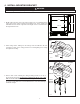
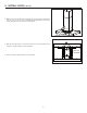
4. INSTALL MOUNTING BRACKET VQ0010 ! WARNING When building framework, always follow all applicable construction codes and standards. 10¼" 1. Modify ceiling structure over hood location. Install 2" x 4" cross framing between ceiling joists using ceiling mounting bracket dimensions shown at right. The framework must be sized to support the total weight of the hood and should not be larger than 9¾" x 9¾". 10¼" 93⁄8 " 103⁄8 " MAX. 9¾" 93⁄8 " 103⁄8 " HK0062A CEILING JOISTS 2.
5. ASSEMBLE ANGLE BRACKETS 1. Assemble 4 angle brackets to the ceiling mounting bracket using 16 no.10-32 x 1/2" quadrex screws (4 per angle bracket). HD0421 2. Determine angle brackets length based upon ceiling height and desired height of hood above cooktop. If required, assemble a second set of 4 angle brackets to the upper angle bracket set according to the length needed. Use 16 no. 10-32 x 1/2" quadrex screws and 16 no. 10-32 lock nuts (4 at each angle bracket connection). FOR 10-FT.
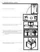
6. REMOVE HYBRID FILTERS Rest the range hood on a table. Protect the table to avoid damaging it. Remove tape on filters. Lift filters by pushing them towards the back of the hood (opposite to control side) and flip, then set filters aside. HO0349 7. INSTALL GLASS PANELS (SBN MODEL ONLY) The SBN hood model decorative glass panels are sold separately and have to be installed before completing the hood installation. 1. Carefully remove glass panel from its packaging.
. PREPARE HOOD (ALL MODELS) 1. From inside the hood, disconnect the blower. HE0063 ELECTRICAL COMPARTMENT RETAINING SCREW 2. Remove the electrical box cover retaining screw. Set cover and screw aside. HE0062 3. Turn the hood over and remove blower box 8 retaining screws (only 4 out of 8 screws illustrated at right). Set hood and screws aside. HD0425 SCREW LOCATIONS 1 2 4. Lift flap located on top right hand corner of blower box (1) to ease wire clamp installation (included).
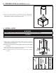
8. PREPARE HOOD (ALL MODELS) (CONT’D) 6. Measure the required length of 8" round metal duct from the adapter/damper to the ductwork rough-in in the ceiling. Connect this section of duct to the adapter/damper and seal joint with metal foil duct tape. HJ0067 9. INSTALL HOOD ! WARNING BE CAREFUL when installing the decorative flue and hood, they may have sharp edges. CAUTION DO NOT REMOVE the protective plastic film covering the decorative flue (upper and lower) and the hood yet. 1.
9. INSTALL HOOD (CONT’D) 4. Attach the hood to the blower box using the 8 screws previously removed at step 8.3 (only 4 out of 8 screws are illustrated at right). Make sure that the house wiring goes into the electrical compartment. HD0426 SCREW LOCATIONS SCREW LOCATIONS 5. Slide the lower flue down on top of the hood and secure from inside the hood using 4 no. 8 x 3/8" quadrex screws (included). ELECTRICAL COMPARTMENT 6. Remove protective plastic film from hood and flues.
10. CONNECT WIRING ! WARNING Risk of electric shock. Electrical wiring must be done by qualified personnel in accordance with all applicable codes and standards. Before connecting wires, switch power off at service panel and lock service disconnecting means to prevent power to be switched on accidentally. 1. Connect hood power cable to house wiring using provided wire connectors: BLACK to BLACK, WHITE to WHITE and GREEN or BARE wire to GREEN ground screw. DO NOT FORGET TO CONNECT THE GROUND.
. LED LIGHTING The lighting of this hood is produced by two LED modules (included). ! WARNING Do not touch lamps during or soon after operation. Burns may occur. Cannot be replaced by any other type of light bulb or LED module. 13. CARE ! WARNING Before servicing or cleaning the unit, switch power off at service panel and lock service panel to prevent power from being switched on accidentally.
14. OPERATION Always turn your hood on before you begin cooking to establish an air flow in the kitchen. Let the blower run for a few minutes to clear the air after you turn off the range. CAUTION After a power failure or during the range hood power up, a 5-second booting sequence is executed. Wait for the control backlighting to turn off before use. A C D B HC0052 A. DELAY BUTTON/CONTROL LOCK (DOUBLE FUNCTION BUTTON): i.
. OPERATION (CONT’D) D. LIGHT BUTTON/BACKLIGHTING COLOR (DOUBLE FUNCTION BUTTON): i. This button allows three different lighting levels according to your needs. Press once for full intensity, twice for intensity level 2, and once more for nightlight. To turn off the lights, press once more. If desired, when the lights are on, press and maintain the light button for 1 second; lights will be turned off.
16. SERVICE PARTS 13 14 12 15 1 2 3 11 4 10 6 5 7 8 9 HL0449 KEY DESCRIPTION PART NO. NO. 1 SV09956XX* FRONT GLASS PANEL 2 SV22427 ELECTRONIC CONTROL 3 SV21221 POWER UNIT 4 SV20816 PCB FOR REMOTE CONTROL 5 SV09022 TRANSFORMER 6 SV08582 INTERNAL BLOWER 7 62248 LED DRIVER AND CONNECTION HARNESS 8 62612 LED MODULE (1) 9 SV62053 HYBRID FILTER 15.875” X 14” x 0.
17. WARRANTY FIVE-YEAR LIMITED WARRANTY FOR BEST® PRODUCTS Warranty Period and Exclusions: Broan-NuTone, LLC (the “Company”) warrants to the consumer purchaser of its product (“you”) that the product (the “Product”) will be free from material defects in the materials or its workmanship for a period of five (5) years from the date of original purchase (or such longer period as may be required by applicable law) or a period of two (2) years from the date of service for any labor provided on the Product.
GUIDE D’INSTALLATION HB0117 SÉRIE ICB3I ! CONÇUE POUR USAGE RÉSIDENTIEL SEULEMENT ! LIRE ET CONSERVER CES DIRECTIVES INSTALLATEUR : LAISSER CE GUIDE AU PROPRIÉTAIRE. PROPRIÉTAIRE : DIRECTIVES D’UTILISATION ET D’ENTRETIEN AUX PAGES 12 À 14. BEST; Hartford, Wisconsin www.BestRangeHoods.com 800 558-1711 BEST; Drummondville, QC, Canada www.BestRangeHoods.ca 866 737-7770 23866 rév.
! AVERTISSEMENT ! AFIN DE RÉDUIRE LES RISQUES D’INCENDIE, D’ÉLECTROCUTION OU DE BLESSURES CORPORELLES, SUIVEZ LES DIRECTIVES SUIVANTES : AVERTISSEMENT AFIN D’ÉVITER TOUT RISQUE DE BLESSURES LORS D’UN FEU DE CUISINIÈRE, SUIVEZ CES DIRECTIVES* : 1. Étouffez les flammes avec un couvercle hermétique, une tôle à biscuits ou un plateau métallique et ensuite, éteignez le brûleur. PRENEZ SOIN D’ÉVITER les brûlures. SI LES FLAMMES NE S’ÉTEIGNENT PAS IMMÉDIATEMENT, ÉVACUEZ LES LIEUX ET APPELEZ LES POMPIERS. 2.
! AVERTISSEMENT Cette hotte est munie d’un récepteur radio (télécommande optionnelle vendue séparément). Tous changements ou modifications qui ne sont pas approuvés par la partie responsable de la conformité pourraient annuler la possibilité d’opérer l’équipement. La télécommande a été testée et est en accord avec les limites de la Classe B appareil numérique et est conforme au chapitre 15 des règlements FCC et ICES-003 canadien.
2. PRÉPARATION DE L’INSTALLATION VQ0010 ! AVERTISSEMENT Il est recommandé de porter des lunettes et des gants de sécurité lors de l’installation, de l’entretien et de la réparation de cet appareil. NOTE : Avant de commencer l’installation, vérifier le contenu de la boîte. Si des pièces sont manquantes ou endommagées, contacter le manufacturier.
4. INSTALLATION DU SUPPORT DE MONTAGE VQ0010 ! AVERTISSEMENT Lors de la construction de la charpente, toujours suivre les codes et standards de construction en vigueur. 10¼ PO 1. Modifier la structure du plafond au-dessus de l’emplacement de la hotte. Installer des traverses en 2 po x 4 po entre les solives du plafond, selon les dimensions du support de montage illustrées ci-contre.
5. ASSEMBLAGE DES ÉQUERRES 1. Assembler 4 équerres au support de montage à l’aide de 16 vis quadrex n° 10-32 x 1/2 po (4 par équerres). HD0421 2. Déterminer la longueur des équerres d’après la hauteur du plafond et celle de l’emplacement de la hotte au-dessus de la surface de cuisson. Si nécessaire, assembler un second ensemble de 4 équerres à l’ensemble d’équerres supérieur selon la longueur requise.
6. RETRAIT DES FILTRES HYBRIDES Poser la hotte sur une table. Protéger la table pour éviter de l’endommager. Retirer le ruban adhésif des filtres. Soulever les filtres en les poussant vers l’arrière (à l’opposé de la commande) et en les dégageant de la hotte, puis les mettre de côté. HO0349 7. INSTALLATION DES FAÇADES DE VERRE (MODÈLE SBN SEULEMENT) Les façades de verre décoratives du modèle de hotte SBN sont vendues séparément et doivent être installées avant de compléter l’installation. 1.
8. PRÉPARATION DE LA HOTTE (TOUS LES MODÈLES) 1. Par l’intérieur de la hotte, débrancher le ventilateur. HE0063 VIS DU COUVERCLE DU COMPARTIMENT ÉLECTRIQUE 2. Retirer la vis de retenue du couvercle du compartiment électrique. Mettre le couvercle et la vis de côté. HE0062 3. Retourner la hotte et retirer les 8 vis de retenue du boîtier du ventilateur (seulement 4 des 8 vis sont illustrées ci-contre). Mettre la hotte et les vis de côté.
8. PRÉPARATION DE LA HOTTE (TOUS LES MODÈLES) (SUITE) 6. Mesurer la longueur de conduit métallique rond de 8 po requise entre l’adaptateur/volet et le conduit du plafond. Raccorder cette longueur de conduit à l’adaptateur/volet et sceller le joint avec du ruban adhésif de métal. HJ0067 9. INSTALLATION DE LA HOTTE VQ0010 ! AVERTISSEMENT SOYEZ PRUDENT lors de l’installation du conduit décoratif et de la hotte, il pourrait y avoir des arêtes vives.
9. INSTALLATION DE LA HOTTE (SUITE) 4. Fixer la hotte au boîtier du ventilateur à l’aide des 8 vis précédemment retirées à l’étape 8.3 (seulement 4 des 8 vis sont illustrées ci-contre). S’assurer que le câble résidentiel s’insère dans le compartiment électrique. HD0426 EMPLACEMENT DES VIS EMPLACEMENT DES VIS 5. Glisser le conduit décoratif inférieur sur le dessus de la hotte et le fixer de l’intérieur de la hotte à l’aide de 4 vis quadrex n° 8 x 3/8 po (incluses). COMPARTIMENT ÉLECTRIQUE 6.
10. BRANCHEMENT ÉLECTRIQUE VQ0010 ! AVERTISSEMENT Risque d’électrocution. Le raccordement électrique doit être effectué par du personnel qualifié conformément aux codes et aux standards. Avant d’effectuer le branchement, coupez l’alimentation électrique au panneau de distribution et verrouillez-le pour éviter sa mise en marche accidentelle. 1.
12. ÉCLAIRAGE À DEL L’éclairage de cette hotte est produit par 2 modules DEL (inclus). VQ0010 ! AVERTISSEMENT Ne pas toucher aux modules DEL durant ou peu après leur utilisation. Peuvent causer des brûlures. Ne peuvent être remplacés par aucun autre type d’ampoule ou de module à DEL. 13. ENTRETIEN VQ0010 ! AVERTISSEMENT Avant de nettoyer ou de réparer l’appareil, coupez le courant au panneau de distribution et verrouillez-en l’accès afin d’éviter sa remise en marche accidentelle.
14. FONCTIONNEMENT Toujours mettre en marche la hotte avant de commencer la cuisson afin d’établir une circulation de l’air dans la cuisine. Aussi, laisser la hotte fonctionner quelques minutes après l’arrêt de la cuisinière afin d’aérer. ATTENTION Après une panne de courant ou lors de la mise sous tension de la hotte, une séquence de démarrage de 5 secondes est effectuée. Attendre que le rétroéclairage de la commande soit éteint avant d’utiliser cette dernière. A C D B HC0052 A.
14. FONCTIONNEMENT (SUITE) D. BOUTON D’ÉCLAIRAGE/COULEUR DU RÉTROÉCLAIRAGE (BOUTON DOUBLE FONCTION) : i. Cette hotte offre trois niveaux d’éclairage différents. Appuyer une fois sur ce bouton pour un éclairage pleine intensité, deux fois pour le niveau 2 et une fois de plus pour la veilleuse. Appuyer une autre fois pour éteindre les lumières. Si désiré, lorsque les lumières sont allumées, appuyer et maintenir la pression pendant 1 seconde; les lumières s’éteindront.
16.
17.
INSTRUCCIONES DE INSTALACIÓN HB0117 SERIE ICB3I ! CONCEBIDO SÓLO PARA USO DOMÉSTICO ! LEER Y CONSERVAR ESTAS INSTRUCCIONES INSTALADOR: DEJAR ESTE MANUAL AL PROPIETARIO. PROPIETARIO: INSTRUCCIONES DE UTILIZACIÓN Y MANTENIMIENTO EN LAS PÁGINAS 12-14. BEST; Hartford, Wisconsin www.BestRangeHoods.com 800-558-1711 BEST; Drummondville, QC, Canada www.BestRangeHoods.ca 866-737-7770 23866 rev.
! ADVERTENCIA ! PARA REDUCIR EL RIESGO DE INCENDIO, CHOQUE ELÉCTRICO O HERIDAS CORPORALES, SIGA LAS INDICACIONES SIGUIENTES: ADVERTENCIA PARA REDUCIR EL RIESGO DE LESIONES PERSONALES EN CASO DE INCENDIO DE LA GRASA ACUMULADA EN LA PARTE SUPERIOR DE LA COCINA, SIGA ESTAS INDICACIONES*: 1. Utilice este aparato sólo en la forma prevista por el fabricante. Si tiene preguntas, póngase en contacto con el fabricante en la dirección o número de teléfono indicados en la garantía. 1.
0 ! ADVERTENCIA Esta campana está equipada con un receptor de RF (control remoto opcional se vende por separado). Los cambios o modificaciones no aprobadas expresamente por la parte responsable del cumplimiento podrían anular la autoridad del usuario para operar el equipo. Este control remoto ha sido probado y cumple con los límites establecidos para un dispositivo digital de clase B, acorde a la parte 15 del Reglamento de la FCC e ICES-003 canadiense.
2. PREPARACIÓN DE LA INSTALACIÓN VQ0010 ! ADVERTENCIA Se aconseja llevar lentes y guantes de seguridad para instalar, reparar o limpiar la unidad. NOTA: Antes de comenzar la instalación, verificar el contenido de la caja. Si alguna pieza falta o está dañada, póngase en contacto con el fabricante.
4. INSTALE EL SOPORTE DE MONTAJE VQ0010 ! ADVERTENCIA Al construir una estructura de madera, siga siempre todos los códigos y normas de construcción correspondientes. 10¼" 1. Modifique la estructura del techo en la ubicación de la campana. Instale un armazón de 2" x 4" entre las viguetas del techo utilizando para ello las dimensiones del soporte de montaje en el techo que se muestran a la derecha.
5. MONTE LOS SOPORTES DE ESCUADRA 1. Monte 4 soportes de escuadra en el soporte de montaje en el techo con 16 tornillos quadrex n.o 10-32 x 1/2" (4 por soporte de escuadra). HD0421 2. Determine la longitud de los soportes de escuadra basándose en la altura del techo y en la altura deseada de la campana por encima de la superficie de cocción. Si es necesario, monte un segundo conjunto de 4 soportes de escuadra sobre el conjunto superior de soportes de escuadra, según la longitud necesaria.
6. QUITE LOS FILTROS HÍBRIDOS Coloque la campana sobre una mesa. Proteja la mesa para evitar que se dañe. Quite la cinta que hay sobre los filtros. Quite los filtros empujándolos hacia la parte posterior de la campana (lado opuesto al lado de los controles), voltéelos y póngalos a un lado. HO0349 7. INSTALACIÓN DE LOS PANELES DE VIDRIO (SERIE SBN SOLAMENTE) Los paneles de vidrio para el modelo SBN estan vendidas aparte y deben ser instalados antes de completar la instalación. 1.
8. PREPARE LA CAMPANA (TODOS LOS MODELOS) 1. Desconecte el ventilador desde el interior de la campana. HE0063 TORNILLO DE RETENCIóN DEL COMPARTIMENTO ELÉCTRICO 2. Retire el tornillo de sujeción de la tapa de la caja eléctrica. Ponga a un lado la tapa y el tornillo. HE0062 3. Gire la campana y quite los 8 tornillos que sujetan la caja del ventilador (a la derecha sólo se muestran 4 de los 8 tornillos). Ponga a un lado la campana y los tornillos. HD0425 UBICACIóN DE LOS TORNILLOS 1 2 4.
8. PREPARE LA CAMPANA (TODOS LOS MODELOS) (CONT.) 6. Mida la longitud necesaria de conducto metálico redondo de 8" entre el adaptador/compuerta y el conducto del techo. Conecte esta sección del conducto al adaptador/compuerta y selle la junta con cinta adhesiva metálica. HJ0067 9. INSTALE LA CAMPANA VQ0010 ! ADVERTENCIA TENGA CUIDADO al instalar la chimenea decorativa y la campana, pueden tener bordes cortantes.
9. INSTALE LA CAMPANA (CONT.) 4. Fije la campana a la caja del ventilador utilizando los 8 tornillos extraídos anteriormente en la etapa 8.3 (en la ilustración de la derecha sólo se muestran 4 de los 8 tornillos). Asegúrese de que el cableado de la casa entra en el compartimento eléctrico. HD0426 UBICACIóN DE LOS TORNILLOS UBICACIóN DE LOS TORNILLOS 5.
10. CONEXIÓN DEL CABLEADO VQ0010 ! ADVERTENCIA Riesgo de choque eléctrico. La conexión eléctrica debe hacerla personal competente con arreglo a los códigos y normas en vigor. Antes de conectar los hilos, corte la alimentación en el tablero de servicio y bloquee los medios de desconexión para impedir que la corriente se conecte accidentalmente. 1. Con los conectadores, conecte el cable de la campana al cable de conexión doméstico.
12. ILUMINACIÓN LED La luz de esta campana proviene de dos módulos LED (incluidos). VQ0010 ! ADVERTENCIA No toque los modulos LED cuando estén encendidos o poco después de apagarlas. Podría quemarse. No es sustituible por ningún otro tipo de lámpara o de módulo LED. 13. CUIDADO VQ0010 ! ADVERTENCIA Antes del mantenimiento o de la limpieza del aparato, apague la alimentación en el tablero de servicio y bloquee el tablero para evitar que se conecte la corriente accidentalmente.
14. FUNCIONAMIENTO Ponga en marcha siempre la campana antes de empezar a cocinar para crear una corriente de aire en la cocina. Deje que el ventilador funcione durante unos minutos para limpiar el aire una vez apagada la cocina. PRECAUCIÓN Después de una interrupción de la alimentación eléctrica o durante el encendido de la campana se produce una secuencia de arranque de 5 segundos. Espere a que la retroiluminación del control se apague antes de usar el aparato. A C D B HC0052 A.
14. FUNCIONAMIENTO (CONT.) D. BOTÓN DE LA LUZ/COLOR DE LA RETROILUMINACIÓN (BOTÓN DE DOBLE FUNCIÓN): i. Este botón permite tres niveles de iluminación diferentes según sus necesidades. Presione una vez para obtener la intensidad máxima, dos veces para la intensidad intermedia, y una vez más para la luz nocturna. Para apagar las luces, presione una vez más. Si lo desea, cuando las luces están encendidas, mantenga presionado el botón de la luz durante 1 segundo y las luces se apagarán.
16. PIEZAS DE RECAMBIO 13 14 12 15 1 2 3 11 4 10 6 5 7 8 9 HL0449 N.o N.o PIEZA DESCRIPCIóN 1 SV09956XX* PANEL DE VIDRIO DELANTERO 2 SV22427 CONTROL ELECTRóNICO 3 SV21221 UNIDAD DE ALIMENTACIóN 4 SV20816 PLACA DE CIRCUITOS IMPRESOS PARA EL CONTROL REMOTO 5 SV09022 TRANSFORMADOR 6 SV08582 VENTILADOR INTERNO 7 62248 MóDULO DE ALIMENTACIóN LED Y MAZO DE CABLES DE CONEXIóN 8 62612 MóDULO LED (1) 9 SV62053 FILTRO HíBRIDO 15.875" X 14" x 0.
17.