INSTALLATION INSTRUCTIONS HB0063 IP29M SERIES ! INTENDED FOR DOMESTIC COOKING ONLY ! READ AND SAVE THESE INSTRUCTIONS INSTALLER: LEAVE THIS MANUAL WITH HOMEOWNER. HOMEOWNER: USE AND CARE AND OPERATION INFORMATION ON PAGES 12 TO 14. In USA - BEST® P.O. Box 140, Hartford, WI 53027 In Canada - BEST® 550 Lemire Blvd., Drummondville, QC, J2C 7W9 REGISTER YOUR PRODUCT ON LINE AT: www.bestrangehoods.com/register For additional information — visit www.bestrangehoods.com V08072 rev.
! WARNING ! WARNING TO REDUCE THE RISK OF FIRE, ELECTRIC SHOCK OR INJURY TO PERSONS, OBSERVE THE FOLLOWING: TO REDUCE THE RISK OF INJURY TO PERSONS IN THE EVENT OF A RANGE TOP GREASE FIRE, OBSERVE THE FOLLOWING*: 1. Use this unit only in the manner intended by the manufacturer. If you have questions, contact the manufacturer at the address or telephone number listed in the warranty. 1. 2.
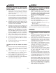
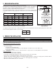
- IP29M SERIES RANGE HOOD SYSTEM INTERIOR BLOWERS Model 437 (High capacity roof cap) Model 441 (10’’ Round wall cap) Model 410 (10” round duct—2 ft. sections) Model 407 (7” round duct—2 ft. sections) Model 423 Model 424 Model 454 (41/2” x 181/2” to (41/2” x 181/2” to (41/2” x 181/2” 10” Round - vertical 10” Round - horiz. to 10” Round front/rear horiz. /right Model 453 (41/2” x 181/2” to 10” Round horiz.
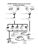
- IP29M SERIES RANGE HOOD SYSTEM IN-LINE AND EXTERIOR BLOWERS Model 437 (High capacity roof cap) Model 643 (8” Round wall cap) Model 441 Model ILB9 (800 cfm) (10” Round wall cap) Model EB12 (1200 cfm) or ILB11 (1100 cfm) or EB15 (1500 cfm) in-line blower Model EB6 (600 cfm) exterior blower (includes two 8” x 12” to or EB9(900 cfm) 10’’ round transitions) exterior blower Model 441 (10” Round wall cap) Model ILB6 (600 cfm) in-line blower (includes two 4½” x 18½” to 10’’ round transitions) Model 418 10” R
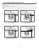
1. SELECT BLOWER OPTION AND INSTALLATION TYPE Either an interior or an exterior blower or in-line blower may be used with this hood. The Best by Broan IP29M Series must be installed with blower models P6, P12, ILB3, ILB6, ILB9, ILB11, EB6, EB9, EB12 or EB15 only. Other blowers cannot be substituted. (Blowers sold separately.) Plan where and how the ductwork will be installed.
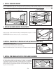
2. MEASURE INSTALLATION Dimensions for the most common installation are shown beside. Framework The minimum hood distance above cooktop must not be less than 30’’. A maximum of flush to ceiling 36” above cooktop is highly recommended for best capture of cooking impurities. Decorative flue Distances over 36” are at the installer and users discretion.
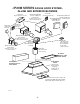
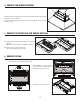
4. PREPARE THE BLOWER HOUSING A B B Detach the blower housing from the hood by removing its both retaining screws (A). Keep the screws for further use. Fold up its both flanges (B). The flanges must be perpendicular to the top of the blower housing. HD0229 5. REMOVE THE FILTERS AND THE GREASE DRIP RAIL 1 A. Remove tape on filters. Remove filters from hood and set aside. NOTE: It is recommended to start with the central one. B. Remove tape on grease drip rail (1). Lift out grease drip rail and set aside.
7. BUILD THE FRAMEWORK ! WARNING When building framework, always follow all applicable construction codes and standards. The framework must be sized to support the total weight of the hood. Refer to the table below for total weight of the hood, according to the type of blower chosen. HOOD WIDTH 42” 54” WITH P6 INTERIOR BLOWER 71 86 WITH P12 LB 7.1 SUGGESTED FRAMEWORK INTERIOR BLOWER 84 99 LB WITH IN-LINE OR LB LB FOR INSTALLATION WITH EXT.
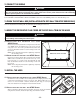
8. INSTALL BLOWER HOUSING Use both screws (A) previously removed in step 4 to assemble the blower housing to the mounting brackets. For installation with decorative flue cover AEIWP Series only, place 4 nuts (B) (from flue cover parts bag) on the pem studs, leaving 1/4” for the hood installation. The blower housing must be installed in such a way that its label (C) will be on the same side as the hood control side. See illustrations below.
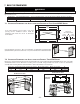
12.CONNECT THE WIRING ! WARNING Risk of electrical shock. Electrical wiring must be done by qualified personnel in accordance with all applicable codes and standards. Before connecting wires, switch power off at service panel and lock service disconnecting means to prevent power to be switched on accidentally. Remove wiring cover from rough-in plate and set aside. Connect BLACK to BLACK, WHITE to WHITE and GREEN or bare wire under GREEN ground screw. Reinstall wiring cover. 13.
16.INSTALL THE BLOWER (INTERIOR OR EXTERIOR BLOWER) Refer to instructions included with blower. Once the blower is installed, plug the blower cord (A) into the female receptacle and the power supply cord (B) onto the male connector inside the hood. A B ! WARNING Do not plug the two cords into each other. HE0078 17.REINSTALL THE PAN CAUTION Remove protective plastic film covering pan sides and tape over halogen lamps. Using a Phillips no. 2 or Robertson no.
19.LIGHT BULBS REPLACEMENT ! WARNING In order to prevent the risk of personal injury, do not install a lamp identified for use only in enclosed fixtures. This hood must use 120 V, 50 W, MR16 with GU10 base or PAR16 with GU10 base, shielded halogen lamps (included). ! WARNING In order to prevent the risk of personal injury, the halogen lamps must be cooled down before removing them. 1 1. To remove lamps, gently push upwards and turn counterclockwise to disengage bulb leads from their grooves.
21.OPERATION Always turn ON your hood before you begin cooking in order to establish an air flow in the kitchen. Let the blower run for a few minutes to clear the air after you turn off the range. This will help keep the whole kitchen cleaner and brighter. 1 2 5 6 max 7 8 9 10 11 3 4 AIR REFRESH NSOR SE HC0032 1.Halogen light push-button INSTEON™ Master Link Mode push-button 2. Blower push-button 3. Enable/Disable functions push-button/ INSTEON™ Erase Link push-button 4.
21.OPERATION (CONT’D) Grease filter reset • Once the grease filter cleaning is done, press on the grease filter reset push-button (item 4 on control illustration) to reset the filter maintenance timer. This will also shut off the grease filter maintenance icon (item 5 on control illustration). Grease filter maintenance indicator • After 30 hours of operation, the grease filter maintenance icon (item 5 on control illustration) appears. This means filters need to be cleaned.
SERVICE PARTS IP29M SERIES 1 5 2 3 4 6 7 8 9 10 11 12 HL0094 KEY PART NO. NUMBER DESCRIPTION 1 V08069 CONTROL PROCESSOR UNIT 2 V08073 PARTICULATES SENSOR 3 V13924 MALE CONNECTOR 4 V13923 FEMALE CONNECTOR 5 V08074 CONTROL INTERFACE 6 V16569 LAMP SHELL, SOCKET AND TRIM ASS’Y 7 V05921 HALOGEN BULBS (50 W, 120 V, PAR16, GU-10) V16967 EVOLUTIONARY™ HYBRID BAFFLE FILTER 8.95” X 8.61” X 1” (INCL. ITEM 10) 8 V16968 EVOLUTIONARY™ HYBRID BAFFLE FILTER 14.95” X 8.61” X 1” (INCL.
WARRANTY WARRANTY ONE-YEAR LIMITED WARRANTY Broan-NuTone LLC (“Broan-NuTone”) warrants to the original consumer purchaser of its products that such products will be free from defects in materials or workmanship for a period of one year from the date of original purchase. THERE ARE NO OTHER WARRANTIES, EXPRESS OR IMPLIED, INCLUDING, BUT NOT LIMITED TO, IMPLIED WARRANTIES OF MERCHANTABILITY OR FITNESS FOR A PARTICULAR PURPOSE.