INSTALLATION INSTRUCTIONS HB0063 IP29M SERIES ! INTENDED FOR DOMESTIC COOKING ONLY ! READ AND SAVE THESE INSTRUCTIONS INSTALLER: LEAVE THIS MANUAL WITH HOMEOWNER. HOMEOWNER: USE AND CARE AND OPERATION INFORMATION ON PAGES 13 TO 16. BEST; Hartford, Wisconsin www.BestRangeHoods.com 800-558-1711 BEST; Drummondville, QC, Canada www.BestRangeHoods.com 866-737-7770 To register your product online or for additional information visit www.BestRangeHoods.com SV08072 rev.
! WARNING ! TO REDUCE THE RISK OF FIRE, ELECTRIC SHOCK OR INJURY TO PERSONS, OBSERVE THE FOLLOWING: WARNING TO REDUCE THE RISK OF INJURY TO PERSONS IN THE EVENT OF A RANGE TOP GREASE FIRE, OBSERVE THE FOLLOWING*: 1. Use this unit only in the manner intended by the manufacturer. If you have questions, contact the manufacturer at the address or telephone number listed in the warranty. 1. SMOTHER FLAMES with a close-fitting lid, cookie sheet or metal tray, then turn off the burner.
- IP29M SERIES RANGE HOOD SYSTEMS INTERIOR BLOWERS MODEL 437 (HIGH CAPACITY ROOF CAP) MODEL 441 (10” ROUND WALL CAP) MODEL 634 OR 644 (ROOF CAP) MODEL 418 (10” ROUND ADJUSTABLE ELBOW, OPTIONAL) MODEL 643 (8” ROUND WALL CAP) 8” ROUND ADJUSTABLE ELBOW, OPTIONAL 8” ROUND MODEL 410 (10” ROUND DUCT— 2 FT.
- IP29M SERIES RANGE HOOD SYSTEMS IN-LINE AND EXTERIOR BLOWERS MODEL 437 (HIGH CAPACITY ROOF CAP) MODEL 441 MODEL ILB9 (800 CFM) (10” ROUND WALL CAP) OR ILB11 (1100 CFM) MODEL EB12 (1200 CFM) IN-LINE BLOWER MODEL EB6 (600 CFM) OR EB15 (1500 CFM) (INCLUDES TWO 8” X 12” TO OR EB9 (900 CFM) EXTERIOR BLOWER 10” ROUND TRANSITIONS) EXTERIOR BLOWER MODEL 643 (8” ROUND WALL CAP) MODEL 441 (10” ROUND WALL CAP) MODEL ILB6 (600 CFM) IN-LINE BLOWER (INCLUDES TWO 4½” X 18½” TO 10” ROUND TRANSITIONS) MODEL 418 (10” R
1. SELECT BLOWER OPTION AND INSTALLATION TYPE Either an interior or an exterior blower or in-line blower may be used with this hood. The Best IP29M Series must be installed with blower models iQ6, P3, P6, iQ12, P12, ILB3, ILB6, ILB9, ILB11, EB6, EB9, EB12 or EB15 only. Other blowers cannot be substituted. (Blowers sold separately.) Plan where and how the ductwork will be installed.
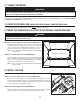
2. MEASURE INSTALLATION Dimensions for the most common installation are shown at right. Framework The minimum hood distance above cooktop must not be less than 30’’. A maximum of 36” flush to ceiling above cooktop is highly recommended for best capture of cooking impurities. Decorative flue Distances over 36” are at the installer and users discretion.
4. PREPARE THE BLOWER HOUSING A B B Detach the blower housing from the hood by removing both retaining screws (A). Keep the screws for further use. Fold up both flanges (B). The flanges must be perpendicular to the top of the blower housing. HD0229 5. REMOVE THE FILTERS AND THE GREASE DRIP RAIL 1 A. Remove tape on filters. Remove filters from hood and set aside. NOTE: It is recommended to start with the center one. B. Remove tape on grease drip rail (1). Lift out grease drip rail and set aside.
7. BUILD THE FRAMEWORK WARNING ! When building framework, always follow all applicable construction codes and standards. The framework must be sized to support the total weight of the hood. Refer to the table below for total weight of the hood, according to the type of blower chosen. WITH IQ6, P3 OR P6 WITH IQ12 OR P12 INTERIOR BLOWER INTERIOR BLOWER WITH IN-LINE OR EXTERIOR BLOWER (ROUGH-IN PLATE ONLY) 42” 71 LB. 84 LB. 52 LB. 54” 86 LB. 99 LB. 67 LB. HOOD WIDTH 7.
8. INSTALL BLOWER HOUSING Use both screws (A) previously removed in step 4 to assemble the blower housing to the mounting brackets. For installation with decorative flue cover AEIP Series only, place 4 nuts (B) (from flue cover parts bag) on the pem studs, leaving 1/4” for the hood installation. The blower housing must be installed in such a way that its label (C) will be on the same side as the hood control side. See illustrations below.
12. CONNECT THE WIRING ! WARNING Risk of electric shock. Electrical wiring must be done by qualified personnel in accordance with all applicable codes and standards. Before connecting wires, switch power off at service panel and lock service disconnecting means to prevent power from being switched on accidentally. Remove wiring cover from rough-in plate and set aside. Connect wires as follow: BLACK to BLACK, WHITE to WHITE and GREEN or bare wire under GREEN ground screw.
16. INSTALL THE BLOWER (INTERIOR OR EXTERIOR BLOWER) Refer to instructions included with blower. Once the blower is installed, plug the blower cord (A) into the female receptacle and the power supply cord (B) onto the male connector inside the hood. ! A WARNING Do not plug the two cords into each other. B HE0078 17.
19. REINSTALL GREASE DRIP RAIL AND BAFFLE FILTERS Reinstall grease drip rail (1). The illustration at right shows how to reinsert the grease drip rail(s) into the range hood. 1 HD0225 CAUTION Remove protective plastic film covering hybrid baffle filters before installing them. Reinstall hybrid baffle filters on the hood. It is recommended to install side filters first and finish with center one. 1. Insert one end of hybrid baffle filter into the front channel of the hood. 2.
20. LIGHT BULBS REPLACEMENT This hood requires shielded halogen lamps (120 V, 50 W, MR16 with GU10 base or PAR16 with GU10 base), included. NOTE: Before using lamps, remove shipping tape on them (if present). ! WARNING Do not touch lamps during or soon after operation. Burns may occur. In order to prevent the risk of personal injury, only install shielded halogen lamps.
22. OPERATION Always turn ON your hood before you begin cooking in order to establish an air flow in the kitchen. Let the blower run for a few minutes to clear the air after you turn off the range. This will help keep the whole kitchen cleaner and brighter. 1 2 5 6 max 7 8 9 10 11 3 4 AIR REFRESH NSOR SE HC0032 1. Halogen light push button/ LinkLogic® Master Link Mode push button 2. Blower push button 3. Enable/Disable functions push button/ LinkLogic® Erase Link push button 4.
23. OPERATION (CONT'D) Grease filter maintenance indicator • After 30 hours of operation, the grease filter maintenance icon (item 5 on control illustration) appears. This means filters need to be cleaned. • Once the grease filter cleaning is done, press on grease filter reset push-button to reset the filter maintenance timer. Interface backlighting • • • • • Off mode (Blower off, Particulates sensor and Air refresh modes disabled): Backlighting is off.
23. OPERATION (CONT'D) ERASE LINK PROCESS A. ACTIVATE THE “LINK” MODE OF THE HOOD Push the LinkLogic link mode push-button (item 4 on control illustration) for 2 seconds; the LinkLogic icon of the interface (item 11 on control illustration) should be visible and backlighting is full intensity at that point. B.
BLACK GREEN WHITE YELLOW COLOR CODE W B ROUGH-IN PLATE G HE0183A NEUTRAL GROUND LINE 120 V SUPPLY B G W Y COMMUNICATION BOARD (INSTEON) W B J6 3 2 1 J5 3 2 1 W B B B W W B B W W Y HEAT SENTRY B M MOTOR W INTERNAL BLOWER ASSEMBLY PARTICULATES SENSOR USER INTERFACE W W Y LIGHT SOCKET W Y LIGHT SOCKET W Y W LIGHT SOCKET Y LIGHT SOCKET W LIGHT SOCKET WY Y LIGHT SOCKET W LIGHT SOCKET WY Y LIGHT SOCKET 25.
BLACK GREEN WHITE YELLOW COLOR CODE W W B J6 3 2 1 J5 3 2 1 ROUGH-IN PLATE G HE0184A NEUTRAL GROUND LINE 120 V SUPPLY B G W Y COMMUNICATION BOARD (INSTEON) GROUND B W B B W W B B PARTICULATES SENSOR W B M MOTOR W REMOTE BLOWER ASSEMBLY W Y HEAT SENTRY USER INTERFACE W W Y LIGHT SOCKET W Y LIGHT SOCKET W Y W LIGHT SOCKET Y LIGHT SOCKET W LIGHT SOCKET WY Y LIGHT SOCKET W LIGHT SOCKET WY Y LIGHT SOCKET 25.
26. WARRANTY WARRANTY ONE-YEAR LIMITED WARRANTY FOR BEST PRODUCTS Broan-NuTone LLC (Broan-NuTone) warrants to the original consumer purchaser of Best products that such products will be free from defects in materials or workmanship for a period of one year from the date of original purchase. THERE ARE NO OTHER WARRANTIES, EXPRESS OR IMPLIED, INCLUDING, BUT NOT LIMITED TO, IMPLIED WARRANTIES OR MERCHANTABILITY OR FITNESS FOR A PARTICULAR PURPOSE.
27. SERVICE PARTS IP29M Series 1 2 5 3 4 6 7 8 9 10 11 HL0216 KEY NO. PART NO.
GUIDE D’INSTALLATION HB0063 SÉRIE IP29M ! CONÇUE UNIQUEMENT POUR LA CUISSON DOMESTIQUE ! LIRE ET CONSERVER CES DIRECTIVES INSTALLATEUR : LAISSER CE GUIDE AU PROPRIÉTAIRE. PROPRIÉTAIRE : DIRECTIVES D’UTILISATION ET D’ENTRETIEN EN PAGES 33 À 36. BEST; Hartford, Wisconsin www.BestRangeHoods.com 800-558-1711 BEST; Drummondville, QC, Canada www.BestRangeHoods.com 866-737-7770 Pour enregistrer votre produit en ligne ou pour obtenir plus d’information, consultez notre site www.BestRangeHoods.com SV08072 rév.
! AVERTISSEMENT ! AFIN DE RÉDUIRE LES RISQUES D’INCENDIE, D’ÉLECTROCUTION OU DE BLESSURES CORPORELLES, SUIVEZ LES DIRECTIVES SUIVANTES : AFIN D’ÉVITER TOUT RISQUE DE BLESSURES LORS D’UN FEU DE CUISINIÈRE, SUIVEZ CES DIRECTIVES* : 1. Étouffez les flammes avec un couvercle hermétique, une tôle à biscuits ou un plateau métallique et ensuite, éteindre le brûleur. PRENEZ SOIN D’ÉVITER LES BRÛLURES. SI LES FLAMMES NE S’ÉTEIGNENT PAS IMMÉDIATEMENT, ÉVACUEZ LES LIEUX ET APPELEZ LES POMPIERS. 2.
- SYSTÈME DE HOTTE DE CUISINIÈRE SÉRIE IP29M VENTILATEURS INTÉRIEURS MODÈLE 437 MODÈLE 441 (CAPUCHON DE TOIT À HAUT RENDEMENT) (CAPUCHON MURAL 10 PO ROND) MODÈLE 634 OU 644 MODÈLE 643 (CAPUCHON DE TOIT) (CAPUCHON MURAL DE 8 PO ROND) MODÈLE 418 (COUDE AJUSTABLE DE 10 PO ROND, OPTIONNEL).
- SYSTÈME DE HOTTE DE CUISINIÈRE SÉRIE IP29M VENTILATEURS EN LIGNE ET EXTÉRIEURS MODÈLE 441 MODÈLE 437 MODÈLE ILB9 (800 PI3/MIN) (CAPUCHON DE TOIT À HAUT RENDEMENT) OU ILB11 (1100 PI3/MIN) (CAPUCHON MURAL 10 PO ROND) MODÈLE EB12 (1200 PI3/MIN) MODÈLE EB6 (600 PI3/MIN) OU EB15 (1500 PI3/MIN) VENTILATEUR EXTÉRIEUR OU EB9 (900 PI3/MIN) VENTILATEUR EN LIGNE (INCLUANT 2 TRANSITIONS DE 8 PO X 12 PO À 10 PO ROND) MODÈLE 643 (CAPUCHON MURAL DE 8 PO ROND) VENTILATEUR EXTÉRIEUR MODÈLE 441 (CAPUCHON MURAL 10 PO RO
1. SÉLECTIONNER L'OPTION VENTILATEUR ET LE TYPE D'INSTALLATION Cette hotte fonctionne autant avec un ventilateur intérieur, en ligne ou extérieur. La hotte de modèle Best de série IP29M doit être installée uniquement avec l’un des ventilateurs suivants : iQ6, P3, P6, iQ12, P12, ILB3, ILB6, ILB9, ILB11, EB6, EB9, EB12 ou EB15 (vendus séparément). Aucun autre ventilateur ne peut être utilisé. Déterminer à quel endroit et de quelle façon les conduits seront installés.
2. MESURER L’INSTALLATION Les dimensions des installations les plus courantes sont indiquées ci-contre. Structure de soutien La distance minimale entre le bas de votre hotte et la surface de cuisson ne doit pas au ras du plafond être inférieure à 30 po. Un maximum de 36 po au-dessus de la surface de cuisson Cheminée décorative est fortement recommandé pour une meilleure évacuation des odeurs de cuisson.
4. PRÉPARER LA CHAMBRE DE VENTILATEUR A B B Détacher la chambre de ventilateur de la hotte en retirant ses 2 vis de retenue (A). Garder les vis pour usage ultérieur. Plier vers le haut ses 2 ailettes (B) de façon à ce qu’elle soient perpendiculaires au-dessus de la chambre de ventilateur. HD0229 5. RETIRER LES FILTRES À CHICANE HYBRIDES ET LA GOUTTIÈRE 1 A. Enlever le ruban adhésif des filtres à chicane hybrides. Retirer les filtres de la hotte et les mettre de côté.
7. CONSTRUIRE LA CHARPENTE ! AVERTISSEMENT Lors de la construction de la charpente, toujours suivre les codes et standards de construction en vigueur. Construire la charpente en fonction du format et du poids total de la hotte. Consulter le tableau ci-dessous pour connaître le poids total de la hotte selon le type de ventilateur choisi.
8. INSTALLER LA CHAMBRE DE VENTILATEUR Utiliser les deux vis (A) retirées précédemment à l’étape 4 pour assembler la chambre de ventilateur aux supports latéraux. Seulement pour une installation avec la cheminée décorative de série AEIP, visser les 4 écrous (B) (provenant du sac de pièces de la cheminée décorative) sur les tiges filetées, en laissant 1/4 po pour l’installation de la hotte.
12. BRANCHEMENT ÉLECTRIQUE ! AVERTISSEMENT Risque d’électrocution. Le raccordement électrique doit être effectué par du personnel qualifié conformément aux codes et aux standards. Avant d’effectuer le branchement, coupez l’alimentation électrique au panneau de distribution et verrouillez-le pour éviter une mise en marche accidentelle. Retirer le couvercle du boîtier électrique de la plaque ventilateur et le mettre de côté.
16. INSTALLER LE VENTILATEUR (INTÉRIEUR OU EXTÉRIEUR) Pour installer le ventilateur, voir les instructions comprises avec celui-ci. Une fois installé, brancher le fil du ventilateur à la prise à 2 alvéoles (A) et le fil d’alimentation électrique de la hotte (B) à la fiche à 3 broches, à l’intérieur de la hotte. ! AVERTISSEMENT A Ne jamais brancher ensemble le fil du ventilateur au fil d’alimentation de la hotte. B HE0078 17.
19. REMETTRE EN PLACE LA GOUTTIÈRE ET LES FILTRES À CHICANE HYBRIDES Réinstaller la gouttière (1). L’image ci-contre illustre la façon de réinsérer la gouttière dans la hotte. 1 HD0225 ATTENTION Avant d’installer les filtres à chicane hybrides, retirer la pellicule de plastique protectrice de ceux-ci. Remettre en place les filtres à chicane hybrides. Il est recommandé d’installer d’abord les filtres situés aux extrémités et de terminer avec celui du centre. 1.
20. REMPLACEMENT DES LAMPES HALOGÈNES L’éclairage de cette hotte est produit par des ampoules halogènes avec écran (120 V, 50 W, MR16 ou PAR16 à culot GU10), incluses. NOTE : Avant d’utiliser les ampoules, retirer le ruban adhésif (si présent). ! AVERTISSEMENT Ne pas toucher aux lampes durant ou peu après leur utilisation. Peuvent causer des brûlures. Afin de réduire le risque de blessures corporelles, n’installer que des ampoules halogènes avec écran.
22. FONCTIONNEMENT Toujours mettre en marche la hotte avant de commencer la cuisson afin d’établir une circulation d’air dans la cuisine. Laisser la hotte fonctionner quelques minutes après la fin de la cuisson afin de nettoyer l’air. Cela aidera à garder la cuisine plus propre et plus fraîche. 1 2 5 6 max 7 NSOR SE 8 9 10 11 3 4 AIR REFRESH HC0032 1. Bouton-poussoir éclairage halogène/ Bouton-poussoir mode LinkLogic® Master Link 2. Bouton-poussoir du ventilateur 3.
22. FONCTIONNEMENT (SUITE) Indicateur d'entretien des filtres à graisses • Après 30 heures de fonctionnement, l’icône d’entretien des filtres à graisses (5 dans l’illustration des commandes) apparaît pour signifier qu’il est temps de les nettoyer. • Une fois le nettoyage des filtres à graisses terminé, appuyer sur le bouton-poussoir de mise à zéro des filtres à graisses pour mettre à zéro la minuterie de l’entretien des filtres.
22. FONCTIONNEMENT (SUITE) PROCESSUS D'EFFACEMENT DU RACCORDEMENT A. ACTIVER LE MODE « LINK » DE LA HOTTE Appuyer sur le bouton-poussoir mode LinkLogic Link (4 dans l’illustration des commandes) durant 2 secondes; l’icône LinkLogic de l’interface (11 dans l’illustration des commandes) devrait apparaître et le rétroéclairage sera à son maximum. B.
BLANC JAUNE NOIR VERT B N PLAQUE VENTILATEUR V HE0183F LA TERRE MISE À NEUTRE LIGNE ALIMENTATION 120 V B J N V CODE DES COULEURS (INSTEON) COMMUNICATION CARTE DE B N J6 3 2 1 J5 3 2 1 B N N N B B N N CAPTEUR DE PARTICULES B M MOTEUR N B VENTILATEUR INTERNE B J HEAT SENTRY INTERFACE DE L’USAGER B B B DOUILLE J DE LAMPE J DOUILLE B J B DE LAMPE J DOUILLE DE LAMPE DOUILLE DE LAMPE DOUILLE B DE LAMPE DOUILLE B J J DE LAMPE DOUILLE B DE LAMPE DOU
BLANC JAUNE NOIR VERT B B N N B N N B B N B B J HEAT SENTRY M MOTEUR N B INTERFACE DE L’USAGER ENSEMBLE DE VENTILATEUR EXTERNE N CAPTEUR DE PARTICULES MISE À LA TERRE J6 3 2 1 J5 3 2 1 PLAQUE VENTILATEUR V HE0184F LA TERRE MISE À NEUTRE LIGNE ALIMENTATION 120 V B J N V CODE DES COULEURS (INSTEON) COMMUNICATION CARTE DE B B B J DE LAMPE DOUILLE J DOUILLE B J B DE LAMPE J DOUILLE DE LAMPE DOUILLE DE LAMPE DOUILLE B DE LAMPE DOUILLE B J J DE LAMPE
25. GARANTIE GARANTIE GARANTIE LIMITÉE DE UN AN DES PRODUITS BEST Broan-NuTone LLC (Broan-NuTone) garantit à l’acheteur consommateur initial de produits Best qu’ils sont exempts de tout défaut dans les matières premières ou la main-d’oeuvre, pour une période de un an à compter de la date d’achat par le consommateur initial. IL N’Y A PAS D’AUTRES GARANTIES, EXPRIMÉES OU IMPLICITES, INCLUANT, MAIS NON LIMITÉES AUX GARANTIES IMPLICITES POUR FIN DE COMMERCIALISATION ET DE CONVENANCE DANS UN BUT PARTICULIER.
26. PIÈCES DE RECHANGE Série IP29M 1 2 5 3 4 6 7 8 9 10 11 HL0216 Nº RÉF.
INSTRUCCIONES DE INSTALACIÓN HB0063 SERIE IP29M ! SÓLO PARA COCINA DOMÉSTICA ! LEA Y CONSERVE ESTAS INSTRUCCIONES INSTALADOR: ENTREGUE ESTE MANUAL AL PROPIETARIO DE LA CASA. PROPIETARIO:INFORMACIÓN SOBRE UTILIZACIÓN, CUIDADOY FUNCIONAMIENTO EN LAS PÁGINAS 53 A 56. BEST; Hartford, Wisconsin www.BestRangeHoods.com 800-558-1711 BEST; Drummondville, Qc, Canada www.BestRangeHoods.com 866-737-7770 Para registrar su producto en línea o para obtener más información, visitar nuestro sitio www.BestRangeHoods.
! ADVERTENCIA ! PARA REDUCIR EL RIESGO DE INCENDIO, DESCARGA ELÉCTRICA O LESIÓN CORPORAL, RESPETE LAS SIGUIENTES INDICACIONES: ADVERTENCIA PARA REDUCIR EL RIESGO DE LESIONES CORPORALES EN EL CASO DE QUE ARDA LA GRASA EN LA PARTE SUPERIOR DE LA COCINA, SIGA ESTAS INDICACIONES*: 1. Utilice esta aparato únicamente de la forma en que indica el fabricante. Si tiene cualquier pregunta, póngase en contacto con el fabricante en la dirección o el teléfono que aparecen en la garantía. 2.
- SYSTEMA DE CAMPANA DE COCINA DE LA SERIE IP29M VENTILADORES INTERIORES MODELO 441 MODELO 437 (CAPUCHÓN DE ALTA CAPACIDAD PARA TEJADO) (CAPUCHÓN MURAL REDONDO DE 10”) MODELO 418 (CODO AJUSTABLE REDONDO DE 10”, OPCIONAL) MODELO 634 O 644 MODELO 643 (CAPUCHÓN PARA TEJADO) (CAPUCHÓN MURAL REDONDO DE 8”) CODO AJUSTABLE REDONDO DE 8”, OPCIONAL TUBO REDONDO 8” MODELO 410 (TUBO REDONDO DE 10”, SECCIONES DE 2') ESTÁNDAR DE ADAPTADOR Y DISPOSITIVO DE CIERRE REDONDO DE 8” MODELO 421 (DISPOSITIVO DE CIERRE (
- SYSTEMA DE CAMPANA DE COCINA DE LA SERIE IP29M VENTILADORES EN LÍNEA Y EXTERIORES MODELO 437 (CAPUCHÓN DE ALTA CAPACIDAD PARA TEJADO) MODELO 643 (CAPUCHÓN MURAL REDONDO DE 8”) MODELO 441 VENTILADOR EN LíNEA ILB9 (800 PCM) O (CAPUCHÓN MURAL REDONDO DE 10”) VENTILADOR EXTERIOR ILB11 (1100 PCM) VENTILADOR EXTERIOR MODELO EB12 (1200 PCM) (COMPRENDE DOS CAMBIOS DE O EB15 (1500 PCM) MODELO EB6 (600 PCM) SECCIÓN DE 8” X 12” A 10” O EB9 (900 PCM) REDONDO) MODELO MODELO 441 (CAPUCHÓN MURAL REDONDO DE 10”) VENT
1. SELECCIÓN DEL TIPO DE VENTILADOR E INSTALACIÓN Esta campana puede emplearse con un ventilador impelente interior, exterior o en línea. La serie IP29M de Best sólo debe instalarse con los modelos iQ6, P3, P6, iQ12, P12, ILB3, ILB6, ILB9, ILB11, EB6, EB9, EB12 o EB15. No deben utilizarse otros ventiladores. Los ventiladores impelentes se venden aparte. Planifique el lugar y la forma en que se instalarán los tubos.
2. MEDIDAS La ilustración de al lado muestra las dimensiones para la instalación habitual. Estructura alineada La distancia mínima entre la campana y la superficie sobre la que se cocina no con el techo debe ser inferior a 30 pulgadas. Se aconseja una distancia máxima de 36 pulgadas Tapa de con respecto a la superficie sobre la que se cocina para captar mejor las impurezas A chimenea decorativa que se desprenden al cocinar.
4. PREPARACIÓN DE LA CAJA DEL VENTILADOR A B B Separe la caja del ventilador de la campana retirando los tornillos de retención (A). Conserve los tornillos. Pliegue los dos rebordes (B). Los rebordes deben quedar perpendiculares a la parte superior de la caja del ventilador. HD0229 5. DESMONTAJE DE LOS FILTROS HÍBRIDOS Y DEL RIEL DE VERTIDO DE LA GRASA 1 A. Retire la cinta de los filtros híbridos. Saque los filtros híbridos de la campana y póngalos aparte.
7. CONSTRUCCIÓN DEL ARMAZÓN ! ADVERTENCIA Siga siempre todos los códigos y normas de construcción aplicables al construir el armazón. Debe prepararse un armazón capaz de soportar todo el peso de la campana. Consulte la tabla siguiente para conocer el peso total de la campana según el tipo de ventilador que se haya elegido.
8. INSTALACIÓN DE LA CAJA DEL VENTILADOR Utilice los tornillos (A) que quitó anteriormente (etapa 4) para instalar la caja del ventilador en los soportes de montaje. Si la instalación se hace con tapa de chimenea decorativa, serie AEIP, coloque 4 tuercas (B) (vienen en la bolsa de piezas de la tapa de chimenea) en los pernos aterrajados, dejando ¼” para instalar la campana. La caja del ventilador debe instalarse de manera que su etiqueta (C) esté en el mismo lado que los mandos de la campana.
12. CONEXIÓN DEL CABLEADO ! ADVERTENCIA Riesgo de choque eléctrico. La conexión eléctrica debe hacerla personal competente con arreglo a los códigos y normas en vigor. Antes de conectar los hilos, corte la alimentación en el tablero de servicio y bloquee los medios de desconexión para impedir que la corriente se conecte accidentalmente. Retire la tapa del cableado de la placa del ventilador y guárdela.
16. INSTALACIÓN DEL VENTILADOR (INTERIOR OR EXTERIOR) Consulte las instrucciones que vienen con el ventilador. Una vez instalado el ventilador, enchufe el cable (A) del ventilador en la toma de corriente hembra y el cable de alimentación (B) al conectador macho dentro de la campana. ! A ADVERTENCIA No enchufe los dos cables uno con otro. B HE0078 17.
19. REINSTALACIÓN DEL RIEL DE VERTIDO DE LA GRASA Y DE LOS FILTROS HÍBRIDOS Vuelva a instalar el riel de vertido de la grasa (1). La ilustración de al lado muestra la forma de colocar el riel en la campana. 1 HD0225 PRECAUCIÓN Antes de instalar los filtros híbridos, retire la película de plástico que los protege. Vuelva a instalar los filtros híbridos en la campana. Se aconseja instalar primero los filtros laterales y terminar con el filtro central. 1.
20. SUSTITUCIÓN DE LAS BOMBILLAS Esta campana debe utilizar bombillas halógenas protegidas de tipo MR16 o PAR16, de 120 V y 50 W con base GU10 (incluidas). NOTA: Antes de utilizar las lámparas, quite la cinta adhesiva que pueda haber sobre ellas. ! ADVERTENCIA No tocar las bombillas durante o justo después de la utilización. Pueden causar quemaduras. Para prevenir el riesgo de lesiones corporales, instale solamente bombillas halógenas protegidas.
22. FUNCIONAMIENTO Ponga en marcha siempre la campana antes de empezar a cocinar para generar una corriente de aire en la cocina. Deje en marcha el ventilador durante unos minutos para renovar el aire una vez que haya apagado la cocina. Esto ayudará a que toda la cocina esté más limpia y despejada. 1 2 5 6 max 7 NSOR SE 8 9 10 11 3 4 AIR REFRESH HC0032 1. Botón pulsador de encendido y apagado de las luces halogenas/ Botón pulsador modo Master Link de LinkLogic® 2.
22. FUNCIONAMIENTO (CONTINUACIÓN) Indicador de mantenimiento de los filtros de grasa • Tras 30 horas de funcionamiento se enciende el icono de mantenimiento de los filtros de grasa (n.° 5 de la ilustración anterior).Esto significa que hay que limpiar los filtros. • Una vez que se hayan limpiado los filtros de grasa, pulse el botón pulsador de restablecimiento de los filtros de grasa para restablecer el temporizador de mantenimiento de los filtros.
22. FUNCIONAMIENTO (CONTINUACIÓN) ELIMINAR EL PROCESO DE CONEXIÓN A. ACTIVE EL MODO “LINK” DE LA CAMPANA Pulse el botón pulsador del modo “Link” (conexión) de LinkLogic (4 en la ilustración de los controles) durante 2 segundos. Se encenderá el icono LinkLogic de la interfaz (11 en la ilustración de los controles) y el alumbrado de fondo se pone a plena intensidad. B.
TARJETA DE 57 B N PLACA DEL VENTILADOR V HE0183E HILO NEUTRO TIERRA LÍNEA 120 V ALIMENTACIÓN FUENTE DE A B N V CÓDIGOS DE COLORES AMARILLO BLANCO NEGRO VERDE (INSTEON) COMUNICACIÓN B N J6 3 2 1 J5 3 2 1 B N N N B B N N SENSOR DE PARTíCULAS B M MOTOR N B VENTILADOR INTERIOR B A HEAT SENTRY INTERFAZ DEL USUARIO B B B A DE LUZ B A B DE LUZ CASQUILLO A DE LUZ DE LUZ CASQUILLO A CASQUILLO CASQUILLO B DE LUZ CASQUILLO B A A DE LUZ CASQUILLO B DE LUZ
A B N V 58 CÓDIGOS DE COLORES AMARILLO BLANCO NEGRO VERDE (INSTEON) B N B N J6 3 2 1 J5 3 2 1 PLACA DEL VENTILADOR V HE0184E HILO NEUTRO TIERRA 120 V LÍNEA ALIMENTACIÓN FUENTE DE TARJETA DE COMUNICACIÓN TIERRA N B N N B B N B B A HEAT SENTRY M MOTOR N B CONJUNTO DE VENTILADOR EXTERIOR N SENSOR DE PARTíCULAS INTERFAZ DEL USUARIO B B B A DE LUZ B A B DE LUZ CASQUILLO A DE LUZ DE LUZ CASQUILLO A CASQUILLO CASQUILLO B DE LUZ CASQUILLO B A A DE LUZ CASQ
25. GARANTÍA GARANTÍA GARANTÍA LIMITADA DE UN AÑO DE LOS PRODUCTOS BEST Broan-NuTone LLC (Broan-NuTone) garantiza al consumidor comprador original de Best productos que dichos productos carecerán de defectos en materiales o en mano de obra por un período de un año a partir de la fecha original de compra. NO EXISTEN OTRAS GARANTÍAS, EXPRESAS O IMPLÍCITAS, INCLUYENDO, PERO NO LIMITADAS A, GARANTÍAS IMPLÍCITAS DE COMERCIALIZACIÓN O ACTITUD PARA UN PROPOSITO PARTICULAR.
26. PIEZAS Serie IP29M 1 2 5 3 4 6 7 8 9 10 11 HL0216 N.º REF. N.º DE PIEZA 1 2 3 4 5 6 7 8 9 * * SV08069 SV08073 SV13924 SV13923 SV08074 SV05917 SV09435 SV09434 SV05921 SV61639 SV61640 SV61934 SV61935 SV03435 SV08072 * SV08068 * SV05869 10 11 CTD (ANCH.