
Installation Guide


- 10 -
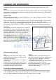
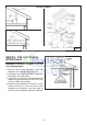
INSTALL SUPPORT SYSTEM
1. At hood location, install 2 x 4 or larger cross
framing between ceiling joists using
dimensions shown.
2. Finish the ceiling surface. Be sure to mark
the location of the ceiling joists and cross
framing.
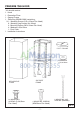
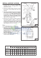
3. Adjust the overall height using the chart below
of the support frame. Loosen and re-tighten
the 4 screws in the height adjustment slots
as necessary. Insert 12 screws (3.9x9.5mm)
located in the Hardware Package (Fig.6)
make sure this a 4” min. overlap between the
upper and lower support legs.
4. Mount the four 6x70mm screws to ceiling in
the location shown in figure 7. Allow 1/4”
clearance between screw head and ceiling
(screws will be tightened later). Make sure
the screws are driven into the center of joists
and framing for maximum strength.
Notes:
a. “-” = Mounting height is not possible.
b. Minimum hood distance above cook top
must not be less than 24”. A maximum of
36” above cook top is highly recommended
for best capture of cooking impurities.
Distances over 36” are at the installer and
the users discretion; and if ceiling height
and flue lenght permit.
c. Requires optional 10’ flue extension,
ducted model AEIPP9SB.
TOP VIEW OF SUPPORT FRAME
10
3
/16” (260mm)
11
7
/16”
(290mm)
CEILING
JOISTS
CROSS FRAMING
SUPPORT
FRAME
10
3
/16”
DRYWALL
MOUNTING
SCREWS
(6x70mm)
HEIGHT ADJUSTMENT
SLOTS
==
11” (280mm)
Ceiling
Height
Hood Distance Above 36” High Cook Top (in.) (see note b)
8 Feet
24
3
/4”
10 Feet
(see note c)
11 Feet
(see note c)
9 Feet
FIG. 6
FIG. 7
MOUNTING
SCREWS
3,9x9,5mm
23
3
/4”22
3
/4”21
3
/4”- - - - - - - - -
---33
3
/4”32
3
/4”31
3
/4”30
3
/4”29
3
/4”28
3
/4”27
3
/4”26
3
/4”25
3
/4”24
3
/4”
48
3
/4”47
3
/4”46
3
/4”45
3
/4”44
3
/4”43
3
/4”42
3
/4”41
3
/4”40
3
/4”39
3
/4”38
3
/4”- -
----56
3
/4”55
3
/4”54
3
/4”53
3
/4”52
3
/4”51
3
/16”50
3
/4”49
3
/4”48
3
/4”
24
25 26 28 29 30 31 32 33 34 35 36 27
Assembled Support Frame Height (in.)