INSTALLATION INSTRUCTIONS HB0123 PK22 AND PKEX22 SERIES ! INTENDED FOR DOMESTIC COOKING ONLY ! READ AND SAVE THESE INSTRUCTIONS INSTALLER: LEAVE THIS MANUAL WITH HOMEOWNER. HOMEOWNER: USE AND CARE INFORMATION ON PAGES 11 TO 13. BEST; Hartford, Wisconsin www.BestRangeHoods.com 800-558-1711 BEST; Drummondville, QC, Canada www.BestRangeHoods.ca 866-737-7770 To register your product online or for additional information visit www.BestRangeHoods.com SV20827 rev.
! WARNING CAUTION 1. For indoor use only. 2. For general ventilating use only. Do not use to exhaust hazardous or explosive materials and vapors. 3. To avoid motor bearing damage and noisy and/or unbalanced impellers, keep drywall spray, construction dust, etc. off power unit. 4. Your power pack motor has a thermal overload which will automatically shut off the motor if it becomes overheated. The motor will restart when it cools down.
- PK22 POWER PACK SYSTEM - MODEL 437 (HIGH CAPACITY ROOF CAP) MODEL 441 (10’’ ROUND WALL CAP) MODEL 418 (10” ROUND ADJUSTABLE ELBOW) MODEL 410 (10” ROUND DUCT — 2 FT.
- PKEX22 POWER PACK SYSTEM - MODEL 437 (HIGH CAPACITY ROOF CAP) MODEL ILB9 (800 CFM) OR ILB11 (1100 CFM) IN-LINE BLOWER (INCLUDES TWO 8” X 12” TO 10’’ ROUND TRANSITIONS) MODEL 643 (8” ROUND WALL CAP) MODEL EB6 (600 CFM) OR EB9 (900 CFM) EXTERNAL BLOWER MODEL EB12 (1200 CFM) OR EB15 (1500 CFM) EXTERNAL BLOWER MODEL 441 (10’’ ROUND WALL CAP) MODEL ILB6 (600 CFM) IN-LINE BLOWER (INCLUDES TWO 4½” X 18½” TO 10’’ ROUND TRANSITIONS) MODEL 418 (10” ROUND ADJUSTABLE ELBOW)— MODEL ILB3 (280 CFM) IN-LINE BLOWER
1. INSTALL DUCTWORK AND ELECTRICAL WIRING For a PKEX22 series power pack, either an external blower or in-line blower must be used. The PKEX22 series power pack must be installed with blower models ILB3, ILB6, ILB9, ILB11, EB6, EB9, EB12 or EB15 only. Other blowers cannot be substituted (blowers sold separately.) If installing external or in-line blower, refer to instructions packed with blower and follow steps 1 to 6, 11 to 16, 18 and up of this manual. Plan where and how the ductwork will be installed.
2. PREPARE THE INSTALLATION (CONT’D) Parts sold separately: - In-line blower assembly model ILB3, ILB6, ILB9 or ILB11. - External blower assembly model EB6, EB9, EB12 or EB15. - Custom hood liner model AL3036, AL3042, AL3948, AL3954, AL4554 or AL4560 (optional). - ACR Series remote control (optional). - Ducts, elbows, wall or roof caps. Refer to pages 3 and 4 for a complete list of venting options and model numbers.
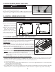
5. CUT HOLE IN CUSTOM HOOD BASE If it is not done yet, cut a hole in the bottom of the cabinet, using the dimensions shown below. POWER PACK WIDTH A 30" 263⁄16" 39" 3415⁄16" 45" 417⁄8" 7/8" 147⁄8" 1513⁄16" 13 NOTE: The 15 ⁄16” and 7/8” measurements show the power pack flange. A HD1159A 6. REMOVE HYBRID BAFFLE FILTERS Remove tape on filters. Remove filters from power pack and set aside. HD0499 7.
9. INSTALL 10" ADAPTER (PK22 SERIES ONLY) Using 2 no. 8 x 3/8” screws from parts bag, assemble the adapter on the top of the power pack. Seal all joints with metal foil duct tape to eliminate air leaks. MOUNTING SCREW LOCATIONS HJ0026 10. INSTALL 10" DAMPER (PK22 SERIES ONLY) Install 10” damper (model 421, provided with PK22 series power packs) inside the vertical ductwork that will be attached to the power pack.
12. CONNECT WIRING (ALL MODELS) ! WARNING Risk of electric shock. Electrical wiring must be done by qualified personnel in accordance with all applicable codes and standards. Before connecting wires, switch power off at service panel and lock service disconnecting means to prevent power from being switched on accidentally. Position the power pack below its custom hood. INTERNAL BLOWERS: Insert the house wiring cable through the wire clamp previously installed in step 8.
15. INSTALL BLOWER (PKEX22 SERIES ONLY) ! WARNING Do not plug the two cords together. To install, see instructions packed with blower. B Once the blower is installed, plug the blower cord (B) into the female receptacle and the power supply cord (A) onto the male connector inside the power pack. A HE0078 16. REINSTALL HYBRID BAFFLE FILTERS CAUTION Remove protective plastic film covering hybrid baffle filters before installing them.
18. LIGHT BULBS This power pack requires shielded halogen lamps (120 V, 50 W, PAR16 with GU10 base, 2 for 30” and 39” width power packs, 3 for 45” width power pack), included. NOTE: Before using lamps, remove shipping tape on them (if present). ! WARNING Do not touch lamps during or soon after operation. Burns may occur. In order to prevent the risk of personal injury, only install shielded halogen lamps.
20. OPERATION Always turn your blower on before you begin cooking to establish an airflow in the kitchen. Let the blower run for a few minutes to clear the air after you turn off the range. A) Blower delay-off button B) ON blower/Speed control button C) OFF blower/ Filter maintenance button D) OFF lighting E) ON light button (3 settings) SPEED HC0016 1 2 A 3 4 B LIGHTING INTENSITY C 1 2 D 3 E A.
21. WARRANTY FIVE-YEAR LIMITED WARRANTY FOR BEST® PRODUCTS Warranty Period and Exclusions: Broan-NuTone, LLC (the “Company”) warrants to the consumer purchaser of its product (“you”) that the product (the “Product”) will be free from material defects in the materials or its workmanship for a period of five (5) years from the date of original purchase (or such longer period as may be required by applicable law) or a period of two (2) years from the date of service for any labor provided on the Product.
22.
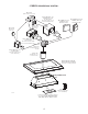
23. SERVICE PARTS Best PK22 Series 1 2 3 16 15 4 5 14 6 REPLACEMENT PARTS AND REPAIRS 13 In order to ensure your unit remains in good working condition, you must use Broan-NuTone genuine replacement parts only. Broan-NuTone genuine replacement parts are specially designed for each unit and are manufactured to comply with all the applicable certification standards and maintain a high standard of safety.
23. SERVICE PARTS (CONT’D) Best PKEX22 Series 12 11 1 REPLACEMENT PARTS AND REPAIRS 10 In order to ensure your unit remains in good working condition, you must use Broan-NuTone genuine replacement parts only. Broan-NuTone genuine replacement parts are specially designed for each unit and are manufactured to comply with all the applicable certification standards and maintain a high standard of safety.
GUIDE D’INSTALLATION HB0123 SÉRIES PK22 ET PKEX22 ! CONÇUES POUR USAGE DOMESTIQUE SEULEMENT ! LIRE ET CONSERVER CES DIRECTIVES INSTALLATEUR : LAISSER CE GUIDE AU PROPRIÉTAIRE. PROPRIÉTAIRE : DIRECTIVES D’UTILISATION ET D’ENTRETIEN EN PAGES 27 À 29. BEST; Hartford, Wisconsin www.BestRangeHoods.com 800 558-1711 BEST; Drummondville, QC, Canada www.BestRangeHoods.ca 866 737-7770 Pour enregistrer votre produit en ligne ou pour obtenir plus d’information, consultez notre site www.BestRangeHoods.
! AVERTISSEMENT ATTENTION 1. Pour une utilisation à l’intérieur seulement. 2. Pour usage domestique seulement. Ne pas utiliser pour évacuer des vapeurs ou des matières dangereuses ou explosives. 3. Afin d’éviter tout dommage au moteur et de débalancer ou de rendre bruyante la roue du moteur, garder votre appareil à l’abri des poussières de gypse et de construction/rénovation, etc. 4.
- SYSTÈME DE HOTTE ENCASTRABLE - SÉRIE PK22 MODÈLE 437 (CAPUCHON DE TOIT À HAUT RENDEMENT) MODÈLE 441 (CAPUCHON MURAL 10 PO ROND) MODÈLE 418 (COUDE AJUSTABLE DE 10 PO ROND) MODÈLE 410 (CONDUIT DE 10 PO ROND — SECTIONS DE 2 PI) MODÈLE 421 (VOLET VERTICAL EN LIGNE DE 10 PO ROND FOURNI AVEC LA HOTTE ENCASTRABLE À VENTILATEUR INTERNE) ADAPTATEUR DE 10 PO ROND (FOURNI AVEC LA HOTTE ENCASTRABLE À VENTILATEUR INTERNE) REVÊTEMENT D’ARMOIRE (OPTIONNEL) AL3036, AL3042, AL3948, AL3954, AL4554 OU AL4560 HOTTE EN
- SYSTÈME DE HOTTE ENCASTRABLE - SÉRIE PKEX22 MODÈLE 437 (CAPUCHON DE TOIT À HAUT RENDEMENT) VENTILATEUR EN LIGNE MODÈLE ILB9 (800 PI3/MIN) OU ILB11 (1100 PI3/MIN) (INCLUANT DEUX VENTILATEUR EXTERNE VENTILATEUR EXTERNE MODÈLE EB6 (600 PI3/MIN) MODÈLE EB12 (1200 PI3/MIN) 8 PO X 12 PO À 10 PO ROND) OU EB9 (900 PI3/MIN) OU EB15 (1500 PI3/MIN) TRANSITIONS DE MODÈLE 441 (CAPUCHON MURAL 10 PO ROND) MODÈLE 643 (CAPUCHON MURAL 8 PO ROND) VENTILATEUR EN LIGNE MODÈLE ILB6 (600 PI3/MIN) (INCLUANT DEUX TRANSITIO
1. INSTALLER LES CONDUITS ET LE CÂBLAGE ÉLECTRIQUE Les hottes encastrables de série PKEX22 doivent être munies d’un ventilateur externe ou en ligne. Elles doivent être installées avec un ventilateur de modèle ILB3, ILB6, ILB9, ILB11, EB6, EB9, EB12 ou EB15 seulement. Aucun autre ventilateur ne peut être utilisé (ventilateurs vendus séparément).
2. PRÉPARER L’INSTALLATION (SUITE) Pièces vendues séparément : - Ventilateur en ligne modèle ILB3, ILB6, ILB9 ou ILB11. Ventilateur externe modèle EB6, EB9, EB12 ou EB15. Revêtement d’armoire, modèle AL3036, AL3042, AL3948, AL3954, AL4554 ou AL4560 (optionnel). Télécommande de série ACR (optionnelle). Conduits, coudes, capuchons de mur ou de toit. Consulter les pages 19 et 20 pour la liste complète des accessoires de ventilation et les numéros de modèle.
5. DÉCOUPER LE TROU DANS LA BASE DE L’ARMOIRE Si ce n’est pas déjà fait, découper le trou dans la base de l’armoire selon les dimensions indiquées ci-dessous. LARGEUR DE LA A HOTTE ENCASTRABLE 30 PO 263⁄16 PO 39 PO 3415⁄16 PO 45 PO 417⁄8 PO 7/8 po 147⁄8 po 1513⁄16 po A NOTE : Les mesures de 1513⁄16 po et de 7/8 po indiquent la bordure de l’appareil. HD1159F 6. RETIRER LES FILTRES À CHICANE HYBRIDES Retirer le ruban adhésif des filtres.
9. INSTALLER L’ADAPTATEUR DE 10 PO (SÉRIE PK22 SEULEMENT) À l’aide de 2 vis n° 8 x 3/8 po fournies dans le sachet de pièces, assembler l’adaptateur sur le dessus de la hotte encastrable. Sceller les joints avec du ruban adhésif de métal pour éliminer les fuites d’air. EMPLACEMENTS DES VIS DE MONTAGE HJ0026 10.
12. BRANCHEMENT ÉLECTRIQUE (TOUS LES MODÈLES) ! AVERTISSEMENT Risque d’électrocution. Le raccordement électrique doit être effectué par du personnel qualifié conformément aux codes et aux standards. Avant d’effectuer le branchement, coupez l’alimentation électrique au panneau de distribution et verrouillez-le pour éviter une mise en marche accidentelle. Placer la hotte encastrable sous son armoire.
15. INSTALLER LE VENTILATEUR (SÉRIE PKEX22 SEULEMENT) ! AVERTISSEMENT Ne jamais brancher ensemble le fil du ventilateur au fil d’alimentation de la hotte. Pour installer le ventilateur, voir les instructions comprises avec celui-ci. Une fois le ventilateur installé, brancher le fil du ventilateur à la prise à 2 alvéoles (B) et le fil d’alimentation électrique de la hotte (A) à la fiche à 3 broches, à l’intérieur de la hotte encastrable. B A HE0078 16.
18. AMPOULES L’éclairage de cette hotte encastrable est produit par des ampoules halogènes avec écran (120 V, 50 W, PAR16 à culot GU10, 2 pour les hottes de 30 et 39 po de largeur, 3 pour la hotte de 45 po de largeur), incluses. NOTE : Avant d’utiliser les ampoules, retirer le ruban adhésif (si présent). ! AVERTISSEMENT Ne pas toucher aux lampes durant ou peu après leur utilisation. Peuvent causer des brûlures.
20. FONCTIONNEMENT Toujours mettre en marche le ventilateur avant de commencer la cuisson afin d’établir une circulation d’air dans la cuisine. Aussi, laisser le ventilateur fonctionner quelques minutes après l’arrêt de la cuisinière afin d’aérer.
21.
22. SCHÉMAS ÉLECTRIQUES N K1 K2 K3 K4 MOTEUR 5 HAUTE B 4 MOY. HAUTE 3 MOY. BASSE 2 BASSE 1 N BL B 4 ~ Q1 - + ~ ~ ~ LAMPE 3 + BASSE TENSION C.A.
23. PIÈCES DE REMPLACEMENT Best série PK22 1 2 3 16 15 4 PIÈCES DE REMPLACEMENT ET SERVICE 5 Pour assurer le bon fonctionnement de votre appareil, vous devez toujours utiliser des pièces d’origine provenant de Broan-NuTone. Les pièces d’origine de Broan-NuTone sont spécialement conçues pour satisfaire toutes les normes de certification de sécurité applicables.
23. PIÈCES DE REMPLACEMENT (SUITE) Best série PKEX22 12 11 1 PIÈCES DE REMPLACEMENT ET SERVICE Pour assurer le bon fonctionnement de votre appareil, vous devez toujours utiliser des pièces d’origine provenant de Broan-NuTone. Les pièces d’origine de Broan-NuTone sont spécialement conçues pour satisfaire toutes les normes de certification de sécurité applicables.
INSTRUCCIONES DE INSTALACIÓN HB0123 SERIES PK22 Y PKEX22 ! EXCLUSIVAMENTE PARA COCINAS DOMÉSTICAS ! LEA ESTAS INSTRUCCIONES Y GUÁRDELAS INSTALADOR: ENTREGUE ESTE MANUAL AL PROPIETARIO DE LA CASA. PROPIETARIO: INFORMACIÓN SOBRE UTILIZACIÓN Y CUIDADO EN LAS PÁGINAS 43 A 45. BEST; Hartford, Wisconsin www.BestRangeHoods.com 800-558-1711 BEST; Drummondville, QC, Canada www.BestRangeHoods.ca 866-737-7770 Para registrar su producto en línea o para obtener más información, visitar nuestro sitio www.
! ADVERTENCIA PRECAUCIÓN 1. Sólo para una utilización en el interior. 2. Sólo para ventilación general. No debe utilizarse para extraer materiales o vapores peligrosos o explosivos. 3. Para evitar daños en el cojinete del motor y que la hélice haga ruido o se desequilibre, mantenga la unidad de alimentación lejos de los vaporizadores de pirca, del polvo de la construcción, etc. 4.
- SISTEMA CON EL GRUPO DE ALIMENTACIÓN - SERIE PK22 MODELO 437 (CAPUCHÓN DE ALTA CAPACIDAD PARA TEJADO) MODELO 441 (CAPUCHÓN MURAL REDONDO DE 10”) MODELO 418 (CODO AJUSTABLE REDONDO DE 10”) MODELO 410 (TUBO REDONDO DE 10”, SECCIONES DE 2 PIES) MODELO 421 (DISPOSITIVO DE CIERRE REDONDO, VERTICAL Y EN LÍNEA DE 10” PROVISTO CON EL GRUPO DE ALIMENTACIÓN DE VENTILADOR INTERNO) ADAPTADOR REDONDO DE 10” (PROVISTO CON EL GRUPO DE ALIMENTACIÓN DE VENTILADOR INTERNO) REVESTIMIENTO DE LA CAMPANA (OPCIONAL) AL303
- SISTEMA CON EL GRUPO DE ALIMENTACIÓN - SERIE PKEX22 MODELO 437 (CAPUCHÓN DE ALTA CAPACIDAD PARA TEJADO) VENTILADOR EN LÍNEA MODELO ILB9 (800 PCM) O ILB11 (1100 PCM) (COMPRENDE DOS CAMBIOS DE SECCIÓN REDONDOS DE 8” X 12” A 10”) VENTILADOR EXTERNO MODELO EB6 (600 PCM) O EB9 (900 PCM) VENTILADOR EXTERNO EB12 (1200 PCM) O EB15 (1500 PCM) MODELO MODELO 441 (CAPUCHÓN MURAL REDONDO DE 10”) MODELO 643 (CAPUCHÓN MURAL REDONDO DE 8”) VENTILADOR EN LÍNEA ILB6 (600 PCM) MODELO (COMPRENDE DOS CAMBIOS DE SEC
1. INSTALACIÓN DE LOS TUBOS Y DE LAS CONEXIONES ELÉCTRICAS Para el grupo de alimentación de la serie PKEX22 debe utilizarse un ventilador externo o en línea. El grupo de alimentación de la serie PKEX22 debe instalarse únicamente con los modelos de ventilador ILB3, ILB6, ILB9, ILB11, EB6, EB9, EB12 o EB15. Estos ventiladores no pueden sustituirse por otros (los ventiladores se venden aparte).
2. PREPARACIÓN DE LA INSTALACIÓN (CONTINUACIÓN) Piezas vendidas aparte: - Conjunto de ventilador en línea, modelo ILB3, ILB6, ILB9 o ILB11. Conjunto de ventilador externo, modelo EB6, EB9, EB12 o EB15. Revestimiento de la campana, modelo AL3036, AL3042, AL3948, AL3954, AL4554 o AL4560 (opcional). Control remoto de la serie ACR (opcional). Tubos, codos, capuchones murales y para el tejado. Consulte las páginas 35 y 36 para ver la lista completa de opciones de ventilación y los números de modelo.
5. CORTE UN ORIFICIO EN LA BASE DE LA CAMPANA Si no está hecho, corte un orificio en la base de la campana, utilizando las dimensiones que aparecen a continuación. ANCHURA DEL GRUPO A DE ALIMENTACIÓN 30" 263⁄16" 39" 3415⁄16" 45" 417⁄8" 7/8" 147⁄8" 1513⁄16" A NOTA: Las dimensiones de 1513⁄16” y 7/8” ilustran el reborde del grupo de alimentación. HD1159A 6. DESMONTAJE DE LOS FILTROS HÍBRIDOS Retire la cinta de los filtros. Saque los filtros del grupo de alimentación y póngalos aparte. HD0499 7.
9. INSTALACIÓN DEL ADAPTADOR DE 10" (SERIE PK22 ÚNICAMENTE) Utilice 2 tornillos n.° 8 x 3/8” de la bolsa de piezas para instalar el adaptador en la parte superior del grupo de alimentación. Precinte todas las juntas con cinta adhesiva metálica para tubos para UBICACIÓN DE LOS TORNILLOS DE INSTALACIÓN que no se escape el aire. HJ0026 10.
12. CONEXIÓN DEL CABLEADO (TODOS LOS MODELOS) ! ADVERTENCIA Riesgo de choque eléctrico. La conexión eléctrica debe hacerla personal competente con arreglo a los códigos y normas en vigor. Antes de conectar los hilos, corte la alimentación en el tablero de servicio y bloquee los medios de desconexión para impedir que la corriente se conecte accidentalmente. Ponga el grupo de alimentación debajo de la campana instalada.
15. INSTALACIÓN DEL VENTILADOR (SERIE PKEX22 ÚNICAMENTE) ! ADVERTENCIA No enchufe un cable en el otro. Para instalar el ventilador, véanse las instrucciones que vienen con él. Enchufe el cable con el enchufe de tres patillas que viene de la placa del ventilador en el conectador macho de tres patillas dentro del grupo de alimentación (A) y el cable con conectador macho de dos patillas que viene de la placa del ventilador en el enchufe de dos patillas dentro del grupo de alimentación (B). B A HE0078 16.
18. BOMBILLAS Este grupo de alimentación necesita bombillas halógenas protegidas (120 V, 50 W, PAR16 con base GU10) (2 para los grupos de alimentación de 30” y 39” de ancho, 3 para el grupo de alimentación de 45” de ancho) (incluidas). NOTA: Antes de utilizar las lámparas, quite la cinta adhesiva que pueda haber sobre ellas. ! ADVERTENCIA No tocar las bombillas durante o justo después de la utilización. Pueden causar quemaduras.
20. FUNCIONAMIENTO Ponga en marcha siempre el ventilador antes de empezar a cocinar para generar una corriente de aire en la cocina. Deje en marcha el ventilador durante unos minutos para renovar el aire una vez que haya apagado la cocina.
21.
22. DIAGRAMAS ELÉCTRICOS NE K1 K2 K3 K4 4 MOTOR 5 ALTA B 4 MED. ALTA 3 MED.
23. PIEZAS Series PK22 de Best 1 2 3 16 15 4 5 14 6 SUSTITUCIÓN DE PIEZAS Y REPARACIÓN 13 Para que la unidad se conserve en buen estado, debe usar repuestos genuinos de Broan-NuTone únicamente. Estas piezas se han diseñado especialmente para cada unidad y se han fabricado conforme a las normas de certificación aplicables y un elevado nivel de seguridad.
23. PIEZAS (CONTINUACIÓN) Serie PKEX22 de Best 12 11 1 SUSTITUCIÓN DE PIEZAS Y REPARACIÓN 10 Para que la unidad se conserve en buen estado, debe usar repuestos genuinos de Broan-NuTone únicamente. Estas piezas se han diseñado especialmente para cada unidad y se han fabricado conforme a las normas de certificación aplicables y un elevado nivel de seguridad.