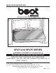
INSTALLATION INSTRUCTIONS HB0061 UP27I and UP27E SERIES ! INTENDED FOR DOMESTIC COOKING ONLY ! READ AND SAVE THESE INSTRUCTIONS INSTALLER: LEAVE THIS MANUAL WITH HOMEOWNER. HOMEOWNER: USE AND CARE AND OPERATION INFORMATION ON PAGES 13 AND 14. In USA - BEST BY BROAN® P.O. Box 140, Hartford, WI 53027 In Canada - BEST BY BROAN® 550 Lemire Blvd., Drummondville, QC, J2C 7W9 REGISTER YOUR PRODUCT ON LINE AT: www.bestbybroan.com/register For additional information - visit www.bestbybroan.com V07855 rev.
! WARNING ! WARNING TO REDUCE THE RISK OF FIRE, ELECTRIC SHOCK OR INJURY TO PERSONS, OBSERVE THE FOLLOWING: TO REDUCE THE RISK OF INJURY TO PERSONS IN THE EVENT OF A RANGE TOP GREASE FIRE, OBSERVE THE FOLLOWING*: 1. Use this unit only in the manner intended by the manufacturer. If you have questions, contact the manufacturer at the address or telephone number listed in the warranty. 1. 2.
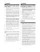
- UP27I SERIES RANGE HOOD SYSTEM INTERIOR BLOWER Model 634 or 644 (roof cap) Model 647 (7” Round wall cap) Model 415 (7” round adjustable elbow, optional) Model 412 transition 3¼” x 10” to 7” round Model 634 or 644 (roof cap) Model 643 (8” Round wall cap) Model 418 8” round adjustable elbow, (optional) Model 407 (7” round duct 2 ft.
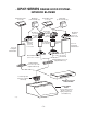
- UP27E SERIES RANGE HOOD SYSTEM IN-LINE AND EXTERIOR BLOWERS Model 437 (High capacity roof cap) Model 441 Model ILB9 (800 cfm) (10” Round wall cap) Model EB12 (1200 cfm) or ILB11 (1100 cfm) or EB15 (1500 cfm) in-line blower Model EB6 (600 cfm) exterior blower (includes two 8” x 12” to or EB9(900 cfm) 10’’ round transitions) exterior blower Model 441 (10” Round wall cap) Model ILB6 (600 cfm) in-line blower (includes two 4½” x 18½” to 10’’ round transitions) Model ILB3 (280 cfm) in-line blower (includes
1. SELECT BLOWER OPTION AND INSTALLATION TYPE 1.1 NON-DUCTED INSTALLATION (ONLY FOR UP27I SERIES HOODS) The non-duct kit ANKUP Series (sold separately) must be installed. This kit fits hood from 30-inch width up to 48-inch width. See installation instructions included with the non-duct kit ANKUP Series. 1.2 DUCTED INSTALLATION Either UP27I or UP27E Series range hoods may be ducted. For a UP27E Series range hood, either an exterior blower or in-line blower may be used.
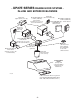
2. PREPARE THE INSTALLATION CAUTION When performing installation, servicing or cleaning the unit, it is recommended to wear safety glasses and gloves. Remove the installation kit from inside the hood.
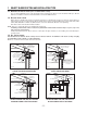
5. REMOVE THE GREASE DRIP RAIL Remove tape on grease drip rail. Lift out grease drip rail and set aside. HD0212 6. REMOVE THE PAN Using a Phillips no. 2 screwdriver, remove the screws retaining the pan (shaded parts on illustration below) to the hood. Remove the pan and set aside. NOTE: There are 2 screw models for UP27I pan retaining screws; the flat end type (A) (n°. 8 x 3/8”) are shorter and located near the front of the hood and the pointed end ones (B) (n°.
7. PREPARE THE CABINET (CONT’D) 7.1 DUCTED INSTALLATION: Cut-out the openings for duct (A) and house wiring (120 V AC)(B) according to the direction of discharge chosen. See figures beside. NOTE: For all UP27I Series (internal blower) range hoods, the cut-out opening for house wiring (120 V AC) can be made in cabinet bottom OR wall, no matter the discharge chosen (horizontal or vertical).
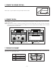
8. PREPARE THE HOOD (CONT’D) 8.1 UP27I SERIES RANGE HOOD (INTERNAL BLOWER) (CONT’D) VERTICAL DISCHARGE (CONT’D) Using 4 no. 8 x 3/8” screws provided with hood, secure the chosen adapter/damper to the top of the hood. Remove tape from damper flap. HD0201 Seal the adapter/damper to the hood using duct tape. HD0202 HORIZONTAL DISCHARGE (DUCTED INSTALLATION ONLY) The UP27I Series range hoods are factory set to exhaust vertically.
8. PREPARE THE HOOD (CONT’D) 8.1 UP27I SERIES RANGE HOOD (INTERNAL BLOWER) (CONT’D) HORIZONTAL DISCHARGE (DUCTED INSTALLATION ONLY)(CONT’D) TOP Using 3 no. 8 x 3/8” screws provided with hood, secure the adapter/damper on the back of the hood. Remove tape from damper flap. OF HOOD ADAPTER/DAMPER SCREW LOCATION BACK OF HOOD HD0204 Seal the adapter/damper and the metal shut-off plate to the hood using duct tape. HD0205 8.
10.INSTALL THE HOOD Place the hood at its location. Using a pen, mark the position of the screw (smaller part of the keyholes [A]). Remove the hood and install (4) 1/2” double thread screws at marked positions, leaving a 1/8” gap. Place the hood under the cabinet and slide it in position. Make sure the adapter/damper enters the ducting and the damper opens freely (UP27I Series range hood only), or ensure ducting connects to rough-in plate (UP27E Series range hood only).
13.REINSTALL GREASE DRIP RAIL AND BAFFLE FILTERS Reinstall the grease drip rail. HD0214 CAUTION Remove protective plastic film covering Evolutionary™ hybrid baffle filters before installing them. 13.1 DUCTED INSTALLATION: Reinstall Evolutionary™ hybrid baffle filters on the hood. 13.2 NON-DUCTED INSTALLATION: Slide out and discard the secondary micromesh filters from the back of the baffle filters. Slide in the charcoal filters included in the non-duct kit. Reinstall the baffle filters on the hood.
15.USE AND CARE Evolutionary™ Hybrid Baffle Filters The Evolutionary™ hybrid baffle filters should be cleaned frequently. Use a warm detergent solution. Wash more often if your cooking style generates greater grease—like frying foods or wok cooking. Remove Evolutionary™ hybrid baffle filters by pushing them towards the front of hood and rotating filters downward. Slide out the secondary micromesh filter from the back of each hybrid baffle filter before cleaning. Baffle filters are dishwasher safe.
16.OPERATION (CONT’D) HEAT SENTRY Both UP27I and UP27E series are equipped with a HEAT SENTRY thermostat. • If blower is ON at a lower speed setting and excessive heat is detected above the cooking surface, it turns the blower up to HIGH speed. When the temperature level drops to normal, the blower will return to its original setting. • If blower is OFF and excessive heat is detected above the cooking surface, HEAT SENTRY will turn the blower to HIGH speed.
SERVICE PARTS UP27I MODEL 2 1 23 22 5 6 3 10 21 7 8 20 12 19 18 11 13 16 9 15 14 17 HL0088 KEY PART NO.
SERVICE PARTS UP27E MODEL 6 5 7 1 8 2 3 4 14 9 13 10 12 11 HL0089 KEY PART NO. NUMBER DESCRIPTION 1 V13923 FEMALE CONNECTOR 2 V13924 MALE CONNECTOR 3 V03435 THERMISTOR HEAT SENTRY 4 V07688 KNOB 5 V16966 PLASTIC CONTROL FRAME AND KNOB ASS’Y 6 V07689 TOGGLE SWITCH 7 V07834 ROTARY CONTROL 8 V16569 LAMP SHELL, SOCKET AND TRIM ASS’Y 9 V05921 HALOGEN BULBS (50 W, 120 V, PAR16, GU-10) 10 V08070 SECONDARY MICROMESH FILTER 8.84” X 13.35” V08071 SECONDARY MICROMESH FILTER 14.84” X 13.