INSTALLATION INSTRUCTIONS HB0061 UP27M SERIES ! INTENDED FOR DOMESTIC COOKING ONLY ! READ AND SAVE THESE INSTRUCTIONS INSTALLER: LEAVE THIS MANUAL WITH HOMEOWNER. HOMEOWNER: USE AND CARE AND OPERATION INFORMATION ON PAGES 10 TO 12. BEST; Hartford, Wisconsin www.BestRangeHoods.com 800-558-1711 BEST; Drummondville, QC, Canada www.BestRangeHoods.com 866-737-7770 To register your product online or for additional information visit www.BestRangeHoods.com SV21516 rev.
! WARNING ! TO REDUCE THE RISK OF FIRE, ELECTRIC SHOCK OR INJURY TO PERSONS, OBSERVE THE FOLLOWING: WARNING TO REDUCE THE RISK OF INJURY TO PERSONS IN THE EVENT OF A RANGE TOP GREASE FIRE, OBSERVE THE FOLLOWING*: 1. Use this unit only in the manner intended by the manufacturer. If you have questions, contact the manufacturer at the address or telephone number listed in the warranty. 1. SMOTHER FLAMES with a close-fitting lid, cookie sheet or metal tray, then turn off the burner.
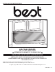
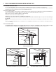
- UP27M SERIES RANGE HOOD SYSTEMS INTERIOR BLOWERS MODEL 634 OR 644 (ROOF CAP) MODEL 643 (8” ROUND WALL CAP) MODEL 432 8” ROUND ADJUSTABLE ELBOW, OPTIONAL MODEL 408 8” ROUND STANDARD DUCT MODEL 438 8” ROUND ADAPTER/DAMPER (INCLUDED WITH IQ6, P3 AND P6 BLOWER/ROUGH-IN KIT) NON-DUCT KIT FLUE ANKUP27M SERIES UP27M SERIES HOOD (CANOPY WITH INTERNAL BLOWER, CONTROLS & LIGHTING. REQUIRED FOR ALL INSTALLATIONS.
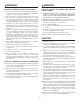
- UP27M SERIES RANGE HOOD SYSTEMS IN-LINE AND EXTERIOR BLOWERS MODEL 437 (HIGH CAPACITY ROOF CAP) MODEL 441 MODEL ILB9 (800 CFM) (10” ROUND WALL CAP) OR ILB11 (1100 CFM) MODEL EB12 (1200 CFM) IN-LINE BLOWER MODEL EB6 (600 CFM) OR EB15 (1500 CFM) (INCLUDES TWO 8” X 12” TO OR EB9 (900 CFM) EXTERIOR BLOWER 10” ROUND TRANSITIONS) EXTERIOR BLOWER MODEL 643 (8” ROUND WALL CAP) MODEL 441 (10” ROUND WALL CAP) MODEL ILB6 (600 CFM) IN-LINE BLOWER (INCLUDES TWO 4½” X 18½” TO 10” ROUND TRANSITIONS) MODEL ILB3 (280
1. SELECT BLOWER OPTION AND INSTALLATION TYPE 1.1 NON-DUCTED INSTALLATION For a non-ducted installation, the interior blower Best model iQ6, P3 or P6 must be used. (Blower sold separately.) The non-duct kit ANKUP27M Series (sold separately) must be installed. This kit fits hood from 30-inch width up to 48-inch width. See installation instructions included with the non-duct kit ANKUP27M Series. 1.
2. PREPARE THE INSTALLATION ! WARNING When performing installation, servicing or cleaning the unit, it is recommended to wear safety glasses and gloves. NOTE: Before proceeding to the installation, check the contents of the box. If items are missing or damaged, contact the manufacturer. Remove the installation kit from inside the hood.
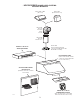
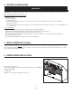
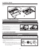
5. REMOVE THE PAN Using a Phillips no. 2 screwdriver, remove the screws retaining the pan (shaded part on illustration at right) to the hood. Remove the pan and set aside. HD0114 6. SELECT BLOWER OPTION (EXTERIOR OR INTERIOR) INTERIOR BLOWER: Follow all subsequent steps of this manual. EXTERIOR BLOWER: Refer to instructions packed with exterior blower and follow steps 8, 10 to 13, then 15 and up of the present manual. 7.
9. INSTALL THE ADAPTER/DAMPER TO ROUGH-IN PLATE (iQ6, P3 AND P6 BLOWERS, DUCTED INSTALLATION ONLY) Attach 8” round adapter and damper to iQ6, P3 or P6 blower rough-in plate. Use metal duct tape to make all joints secure and air-tight. HO0196 10. INSTALL THE ROUGH-IN PLATE TO THE HOOD (ALL BLOWERS) BLOWER PLATE Run power cable to installation location. Refer to the instructions included with the selected blower/rough-in kit (sold separately) for details on installing the rough-in plate.
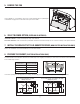
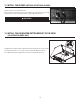
13. INSTALL THE BLOWER (INTERIOR OR EXTERIOR BLOWER) Refer to instructions included with blower. A Once the blower is installed, plug the power supply to the 3-prong male connector (A) and the blower unit into the 2-prong female receptacle (B) inside the hood. ! WARNING Do not plug the two cords into each other. HE0003 14. INSTALL THE CALIBRATION BUTTON BRACKET IN THE HOOD (iQ6 INTERIOR BLOWER ONLY) The iQ6 blower is equipped with a calibration button already mounted to its own bracket.
15. REINSTALL THE PAN Insert the front of the pan inside the hood (), while its front rests on inner front of hood, start mounting the pan by the back retaining screws () (2 or 4 according to hood width), then, screw the front of the pan to the hood using remaining screws (previously removed in step 5). HD0117 16. REINSTALL HYBRID BAFFLE FILTERS CAUTION Remove protective plastic film covering hybrid baffle filters before installing them.
18. USE AND CARE Hybrid Baffle Filters The hybrid baffle filters should be cleaned frequently. Use a warm detergent solution. Wash more often if your cooking style generates greater grease—like frying foods or wok cooking. Remove hybrid baffle filters by pushing them towards the front of hood and rotating filters downward. Baffle filters are dishwasher safe. Allow filters to dry completely before reinstalling them in the hood. Clean all-metal filters in the dishwasher using a non-phosphate detergent.
19. OPERATION Always turn ON your hood before you begin cooking in order to establish an air flow in the kitchen. Let the blower run for a few minutes to clear the air after you turn off the range. This will help keep the whole kitchen cleaner and brighter. 2 1 3 4 HC0030 1. ON/OFF Blower switch 2. Blower speed control 3. ON/OFF Halogen light switch 4. Light intensity control Blower The blower is operated using two (2) controls.
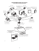
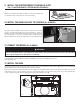
HE0189A ROUGH-IN PLATE G W BLK BLK W W BLK INTERNAL BLOWER ASSEMBLY W BLK M W BLK LIGHT SWITCH BLK W BLK BLK BLU G W Y BLACK BLUE GREEN WHITE YELLOW COLOR CODE LIGHT CONTROL FAN SWITCH BLU Y BLK W W W Y Y Y SPEED CONTROL HS THERMOSTAT BLU LAMP LAMP 13 LAMP LINE NEUTRAL GROUND LAMP 120 VAC 20.
HE0190A ROUGH-IN PLATE G W BLK G BLK W W BLK REMOTE BLOWER ASSEMBLY W BLK M W BLK LIGHT SWITCH BLK W BLK BLK BLU G W Y BLACK BLUE GREEN WHITE YELLOW COLOR CODE LIGHT CONTROL FAN SWITCH BLU Y BLK W W W Y Y Y SPEED CONTROL HS THERMOSTAT BLU LAMP LAMP 14 LAMP LINE NEUTRAL GROUND LAMP 120 VAC 20.
21. SERVICE PARTS UP27M Series 10 11 12 9 5 7 6 8 13 14 15 1 4 2 3 HL0223 KEY NO. 1 2 3 4 5 6 7 8 9 10 11 12 13 14 15 PART NO. DESCRIPTION SV05869 SV61932 SV61933 SV61934 SV61935 SV61691 SV61639 SV61640 SV03435 SV13923 SV13924 SV07688 SV16966 SV03501 SV07689 SV05917 SV09435 SV09434 SV05921 SV21516 BEST LOGO GREASE DRIP RAIL 30” GREASE DRIP RAIL 36” GREASE DRIP RAIL 42” GREASE DRIP RAIL 48” FILTER FILLERS WITH SCREW (PAIR) HYBRID BAFFLE FILTER 8.84" X 8.
22. WARRANTY FIVE-YEAR LIMITED WARRANTY FOR BEST® PRODUCTS Warranty Period and Exclusions: Broan-NuTone, LLC (the “Company”) warrants to the consumer purchaser of its product (“you”) that the product (the “Product”) will be free from material defects in the materials or its workmanship for a period of five (5) years from the date of original purchase (or such longer period as may be required by applicable law) or a period of two (2) years from the date of service for any labor provided on the Product.
GUIDE D’INSTALLATION HB0061 SÉRIE UP27M ! CONÇUE UNIQUEMENT POUR LA CUISSON DOMESTIQUE ! LIRE ET CONSERVER CES DIRECTIVES INSTALLATEUR : LAISSER CE GUIDE AU PROPRIÉTAIRE. PROPRIÉTAIRE : DIRECTIVES D’UTILISATION ET D’ENTRETIEN EN PAGES 26 À 28. BEST; Hartford, Wisconsin www.BestRangeHoods.com 800-558-1711 BEST; Drummondville, QC, Canada www.BestRangeHoods.com 866-737-7770 Pour enregistrer votre produit en ligne ou pour obtenir plus d’information, consultez notre site www.BestRangeHoods.com SV21516 rév.
! AVERTISSEMENT ! AFIN DE RÉDUIRE LES RISQUES D’INCENDIE, D’ÉLECTROCUTION OU DE BLESSURES CORPORELLES, SUIVEZ LES DIRECTIVES SUIVANTES : AVERTISSEMENT AFIN D’ÉVITER TOUT RISQUE DE BLESSURES LORS D’UN FEU DE CUISINIÈRE, SUIVEZ CES DIRECTIVES* : 1. Étouffez les flammes avec un couvercle hermétique, une tôle à biscuits ou un plateau métallique et ensuite, éteindre le brûleur. PRENEZ SOIN D’ÉVITER LES BRÛLURES. SI LES FLAMMES NE S’ÉTEIGNENT PAS IMMÉDIATEMENT, ÉVACUEZ LES LIEUX ET APPELEZ LES POMPIERS. 2.
- SYSTÈME DE HOTTE DE CUISINIÈRE DE SÉRIE UP27M VENTILATEURS INTÉRIEURS MODÈLE 634 OU 644 (CAPUCHON DE TOIT) MODÈLE 643 (CAPUCHON MURAL DE 8 PO ROND) MODÈLE 432 COUDE AJUSTABLE DE 8 PO ROND, OPTIONNEL MODÈLE 408 CONDUIT DE 8 PO ROND, STANDARD CHEMINÉE DU KIT DE RECIRCULATION SÉRIE ANKUP27M MODÈLE 438 ADAPTATEUR/VOLET DE 8 PO ROND (INCLUS AVEC LE VENTILATEUR/PLAQUE VENTILATEUR IQ6, P3 ET P6) HOTTE SÉRIE UP27M (AVEC VENTILATEUR INTÉRIEUR, COMMANDES ET ÉCLAIRAGE. REQUISE POUR TOUTES LES INSTALLATIONS.
- SYSTÈME DE HOTTE DE CUISINIÈRE DE SÉRIE UP27M VENTILATEURS EXTÉRIEURS ET EN LIGNE MODÈLE 437 (CAPUCHON DE TOIT À HAUT RENDEMENT) MODÈLE ILB9 (800 PI3/MIN OU ILB11 (1100 PI3/MIN) MODÈLE 441 (CAPUCHON MURAL DE 10 PO ROND) MODÈLE EB12 (1200 PI3/MIN) MODÈLE EB6 (600 PI3/MIN) OU EB15 (1500 PI3/MIN) OU EB9 (900 PI3/MIN) VENTILATEUR EXTÉRIEUR VENTILATEUR EN LIGNE (INCLUANT 2 TRANSITIONS DE 8 PO X 12 PO À 10 PO ROND) MODÈLE 643 (CAPUCHON VENTILATEUR EXTÉRIEUR MODÈLE 441 (CAPUCHON MURAL 10 PO ROND) MURAL DE
1. SÉLECTIONNER L’OPTION VENTILATEUR ET LE TYPE D’INSTALLATION 1.1 INSTALLATION EN RECIRCULATION Pour une installation sans conduit, la hotte doit être installée avec le ventilateur intérieur Best iQ6, P3 ou P6 (vendu séparément). Le kit de recirculation de série ANKUP27M (vendu séparément) doit être installé. Ce kit convient aux largeurs de hotte allant de 30 po à 48 po inclusivement. Voir les directives d’installation fournies avec le kit de recirculation de série ANKUP27M. 1.
2. PRÉPARER L’INSTALLATION ! AVERTISSEMENT Il est recommandé de porter des lunettes et des gants de sécurité lors de l’installation, de l’entretien et de la réparation de cet appareil. NOTE : Avant de commencer l'installation, vérifier le contenu de la boîte. Si des pièces sont manquantes ou endommagées, contacter le manufacturier. Retirer la trousse d’installation de l’intérieur de la hotte.
5. RETIRER LE CADRE INTÉRIEUR À l’aide d’un tournevis Phillips n° 2, enlever les vis retenant le cadre intérieur (pièce colorée en gris dans l’illustration ci-contre) à la hotte. Retirer le cadre intérieur et le mettre de côté. HD0114 6. CHOISIR LE TYPE DE VENTILATEUR (INTÉRIEUR OU EXTÉRIEUR) VENTILATEUR INTÉRIEUR : Suivre toutes les étapes subséquentes de ce guide.
9. ASSEMBLER L'ADAPTATEUR/VOLET À LA PLAQUE VENTILATEUR (VENTILATEURS iQ6, P3 ET P6, INSTALLATION AVEC CONDUITS SEULEMENT) Assembler l’adaptateur/volet de 8 po à la plaque du ventilateur iQ6, P3 ou P6. Sceller tous les joints avec du ruban à conduits. HO0196 10. INSTALLER LA PLAQUE VENTILATEUR À LA HOTTE (TOUS LES VENTILATEURS) PLAQUE VENTILATEUR Faire cheminer le câble d’alimentation à l’emplacement de la hotte.
13. INSTALLER LE VENTILATEUR (VENTILATEUR INTÉRIEUR OU EXTÉRIEUR) Pour installer le ventilateur, voir les instructions comprises avec celui-ci. Une fois installé, brancher le cordon de la boîte de jonction (A) à la fiche à 3 broches et le ventilateur (B) à la prise derrière le panneau de commande à l’intérieur de la hotte. ! A B AVERTISSEMENT Ne jamais brancher ensemble le fil du ventilateur au fil d’alimentation de la hotte. HE0003 14.
15. REMETTRE EN PLACE LE CADRE INTÉRIEUR Insérer l'avant du cadre à l'intérieur de la hotte (), pendant que l'avant s'appuie sur le nez interne de la hotte, commencer à fixer le cadre avec ses vis de retenue arrière () (2 ou 4 selon la largeur de la hotte), puis visser l'avant du cadre à la hotte avec les vis restantes (retirées précédemment à l'étape 5). HD0117 16.
18. ENTRETIEN Filtres à chicane hybride Les filtres à chicane hybrides doivent être nettoyés fréquemment. Utiliser une solution d’eau chaude et de détergent. Les filtres à chicane doivent être lavés plus souvent si vos habitudes de cuisson génèrent plus de graisse, comme par exemple de la friture ou des aliments sautés au wok. Retirer les filtres en les poussant vers l’avant de la hotte et en les retournant vers le bas. Les filtres à chicane sont lavables au lave-vaisselle.
19. FONCTIONNEMENT Toujours mettre en marche la hotte avant de commencer la cuisson afin d’établir une circulation d’air dans la cuisine. Laisser la hotte fonctionner quelques minutes après la fin de la cuisson afin de nettoyer l’air. Cela aidera à garder la cuisine plus propre et plus fraîche. 2 1 3 4 HC0030 1. Interrupteur Marche/Arrêt du ventilateur 2. Commande de vitesse du ventilateur 3. Interrupteur Marche/Arrêt des lampes halogènes 4.
PLAQUE DU VENTILATEUR V BLA N N BLA BLA N BLA VENTILATEUR INTERNE N M BLA N INTERRUPTEUR DE L’ÉCLAIRAGE N BLA CONTRÔLE DE L’ÉCLAIRAGE N BLA BLE J N V BLANC BLEU JAUNE NOIR VERT CODE DES COULEURS VENTILATEUR INTERRUPTEUR DU BLE N J BLA BLA BLA J J J VITESSE CONTRÔLE DE THERMOSTAT HS BLE LAMPE LAMPE LA TERRE LAMPE LIGNE NEUTRE MISE À LAMPE 120 VCA 20.
PLAQUE DU VENTILATEUR V BLA N V N BLA BLA N BLA VENTILATEUR EXTERNE N M BLA N INTERRUPTEUR DE L’ÉCLAIRAGE N BLA CONTRÔLE DE L’ÉCLAIRAGE N BLA BLE J N V BLANC BLEU JAUNE NOIR VERT CODE DES COULEURS VENTILATEUR INTERRUPTEUR DU BLE N J BLA BLA BLA J J J VITESSE CONTRÔLE DE THERMOSTAT HS BLE LAMPE LAMPE LA TERRE LAMPE LIGNE NEUTRE MISE À LAMPE 120 VCA 20.
21. PIÈCES DE REMPLACEMENT Série UP27M 10 11 12 9 5 7 6 8 13 14 15 1 4 2 3 HL0223 No No DE RÉF.
22.
MANUAL DE INSTALACIÓN HB0061 SERIE UP27M ! SÓLO PARA COCINA DOMÉSTICA ! LEA Y CONSERVE ESTAS INSTRUCCIONES INSTALADOR: ENTREGUE ESTE MANUAL AL PROPIETARIO DE LA CASA. PROPIETARIO:INFORMACIÓN SOBRE UTILIZACIÓN, CUIDADOY FUNCIONAMIENTO EN LAS PÁGINAS 42 A 44. BEST; Hartford, Wisconsin www.BestRangeHoods.com 800-558-1711 BEST; Drummondville, Qc, Canada www.BestRangeHoods.com 866-737-7770 Para registrar su producto en línea o para obtener más información, visitar nuestro sitio www.BestRangeHoods.
! ADVERTENCIA ! ADVERTENCIA PARA REDUCIR EL RIESGO DE LESIONES CORPORALES EN EL CASO DE QUE ARDA LA GRASA EN LA PARTE SUPERIOR DE LA COCINA, SIGA ESTAS INDICACIONES*: PARA REDUCIR EL RIESGO DE INCENDIO, DESCARGA ELÉCTRICA O LESIÓN CORPORAL, RESPETE LAS SIGUIENTES INDICACIONES: 1. Utilice esta aparato únicamente de la forma en que indica el 1. SOFOQUE LAS LLAMAS con una tapa ajustada, una placa o bandeja metálica para hornear galletas, y apague luego el quemador. TENGA CUIDADO PARA EVITAR QUEMADURAS.
- CAMPANAS DE COCINA DE LA SERIE UP27M VENTILADORES INTERIORES MODELO 634 O 644 (CAPUCHÓN PARA TEJADO) MODELO 643 (CAPUCHÓN MURAL REDONDO DE 8”) MODELO 432 CODO AJUSTABLE REDONDO DE 8”, OPCIONAL) MODELO 408 TUBO ESTÁNDAR REDONDO DE 8” CHIMENEA DEL JUEGO PARA INSTALACIÓN SIN TUBOS SERIE ANKUP27M MODELO 438 ADAPTADOR Y DISPOSITIVO DE CIERRE REDONDO DE 8” (PROVISTO CON EL CONJUNTO DE VENTILADOR/PLACA DEL VENTILADOR MODELO IQ6, P3 Y P6) CAMPANA DE LA SERIE UP27M (DOSEL CON VENTILATOR INTERIOR, MANDOS Y LUC
- CAMPANAS DE COCINA DE LA SERIE UP27M VENTILADORES EN LÍNEA Y EXTERIORES MODELO 437 (CAPUCHÓN DE ALTA CAPACIDAD PARA TEJADO) VENTILADOR EN LíNEA ILB9 (800 PCM) O ILB11 (1100 PCM) MODELO 441 (CAPUCHÓN MURAL REDONDO DE 10”) MODELO (COMPRENDE DOS CAMBIOS DE SECCIÓN DE 8” X 12” A 10” REDONDO) VENTILADOR EXTERIOR VENTILADOR EXTERIOR MODELO EB6 (600 PCM) O EB9 (900 PCM) MODELO EB12 (1200 PCM) O EB15 (1500 PCM) MODELO 441 (CAPUCHÓN MURAL REDONDO DE 10”) MODELO 643 (CAPUCHÓN MURAL REDONDO DE 8”) VENTILAD
1. SELECCIÓN DEL TIPO DE VENTILADOR E INSTALACIÓN 1.1 INSTALACIÓN SIN TUBOS Para una instalación sin tubos, la campana debe ser instalada con el ventilador interior Best de modelo iQ6, P3 o P6. Los ventiladores son vende aparte. Debe instalarse el juego para instalación sin tubos, serie ANKUP27M (se vende aparte). Este juego es apropiado a las campanas de 30” a 48” de anchura. 1.
2. PREPARACIÓN DE LA INSTALACIÓN ! ADVERTENCIA Se aconseja llevar anteojos y guantes de seguridad al instalar, reparar o limpiar el aparato. NOTA: Antes de comenzar la instalación, verificar el contenido de la caja. Si alguna pieza falta o está dañada, póngase en contacto con el fabricante. Retire el juego de instalación del interior de la campana.
5. DESMONTAJE DE LA PLACA Utilice un destornillador Phillips n.° 2 para retirar los tornillos que sujetan la placa (parte sombreada de la ilustración al lado) a la campana. Retire placa y póngala a un lado. HD0114 6. SELECCIONE LA OPCIÓN VENTILADOR (INTERIOR O EXTERIOR) VENTILADOR INTERIOR: Siga todas las etapas subsecuentes de este manual. VENTILADOR EXTERIOR: Se refiere a las instrucciones incluidas con el ventilador exterior. Siga las etapas 8, 10 a13, despues 15 y siguiente del presente manual 7.
9. SUJETE EL ADAPTADOR Y DISPOSITIVO DE CIERRE EN LA PLACA DEL VENTILADOR (VENTILADORES iQ6, P3 Y P6, INSTALACIÓN CON TUBOS SOLAMENTE) Sujete el adaptador y dispositivo de cierre redondo de 8” a la placa del ventilador. Utilice cinta adhesiva para tubos metálicos para cerrar las juntas y hacerlas herméticas. HO0196 10. INSTALE LA PLACA DEL VENTILADOR A LA CAMPANA (TODOS LOS VENTILADORES) PLACA DEL VENTILADOR Lleve el cable de alimentación hasta el lugar de la instalación.
13. INSTALACIÓN DEL VENTILADOR (VENTILADOR INTERIOR O EXTERIOR) Consulte las instrucciones que vienen con el ventilador. A Una vez instalado el ventilador, conecte el cable de la caja eléctrica (A) y el cable del ventilador (B) a los enchufes detrás del panel de control al interior de la campana. ! B ADVERTENCIA Jamás conecte el cable eléctrico del ventilador con el enchufe del cable de alimentación. HE0003 14.
15. REINSTALACIÓN DE LA PLACA Introducir la parte delantera de la placa dentro de la campana (), mientras que la parte delantera de la placa se apoya en la parte interna delantera de la campana, comenzar a fijar la placa con los tornillos de fijación trasero () (2 o 4 según el ancho de la campana), después atornillar la parte delantera de la placa a la campana con los tornillos restantes (retirados previamente en el paso 5). HD0117 16.
18. USO Y CUIDADO Filtros híbridos Los filtros híbridos deben limpiarse con frecuencia. Utilice una disolución de detergente con agua templada. Lávelos con mayor frecuencia si su tipo de cocina genera más grasa (alimentos fritos o cocina con wok). Retire los filtros empujándolos hacia la parte trasera de la campana y girándolos hacia abajo. Las placas de filtro pueden lavarse en el lavavajillas. Deje que los filtros sequen completamente antes de volver a instalarlos en la campana.
19. FUNCIONAMIENTO Ponga en marcha siempre la campana antes de empezar a cocinar para generar una corriente de aire en la cocina. Deje en marcha el ventilador durante unos minutos para renovar el aire una vez que haya apagado la cocina. Esto ayudará a que toda la cocina esté más limpia y despejada. 2 1 3 4 HC0030 1. Interruptor de encendido y apagado del ventilado 2. Control de velocidad del ventilador 3. Interruptor de encendido y apagado de las luces halógenas 4.
PLACA DEL HE0189E VENTILADOR V N B N B B B N VENTILADOR INTERIOR N M B N DE LÁMPARA INTERRUPTOR N N B CÓDIGOS DE COLORES AM AMARILLO AZ AZUL B BLANCO N NEGRO V VERDE CONTROL DE LA LUZ VENTILADOR INTERRUPTOR DEL AZ AM N B B B AM AM AM VELOCIDAD CONTROL DE TERMOSTATO HS AZ LÁMPARA LÁMPARA NEUTRO TIERRA LÁMPARA LíNEA HILO LÁMPARA 120 VCA 20.
HE0190E VENTILADOR EXTERIOR B B N CONJUNTO DE V N B PLACA DEL B N VENTILADOR V N M B N DE LÁMPARA INTERRUPTOR N N B CÓDIGOS DE COLORES AM AMARILLO AZ AZUL B BLANCO N NEGRO V VERDE CONTROL DE LA LUZ VENTILADOR INTERRUPTOR DEL AZ AM N B B B AM AM AM VELOCIDAD CONTROL DE TERMOSTATO HS AZ LÁMPARA LÁMPARA NEUTRO TIERRA LÁMPARA LíNEA HILO LÁMPARA 120 VCA 20.
21. PIEZAS Serie UP27M 10 11 12 9 5 7 6 8 13 14 15 1 4 2 3 HL0223 N.o N.o DE REF. PIÈCE 1 SV05869 SV61932 SV61933 SV61934 SV61935 SV61691 SV61639 SV61640 SV03435 SV13923 SV13924 SV07688 SV16966 SV03501 SV07689 SV05917 SV09435 SV09434 SV05921 SV21516 2 3 4 5 6 7 8 9 10 11 12 13 14 15 SV13278 CTD (ANCHURA DE LA CAMP.
22.