Model WC26E For use with Best By Broan Exterior Blower model EB6, EB9, EB12 and EB15; Or In-Line Blower model ILB3, ILB6, ILB9 or ILB11 ENGLISH.....................................2 FRANÇAIS................................15 ESPAÑOL..................................28 BEST BY BROAN P.O.
READ AND SAVE THESE INSTRUCTIONS ! INTENDED FOR DOMESTIC COOKING ONLY ! WARNING TO REDUCE THE RISK OF FIRE, ELECTRIC SHOCK, OR INJURY TO PERSONS, OBSERVE THE FOLLOWING: 1. Use this unit only in the manner intended by the manufacturer. If you have questions, contact the manufacturer at the address or telephone number listed in the warranty. 2. Before servicing or cleaning unit, switch power off at service panel and lock service panel to prevent power from being switched on accidentally.
! CAUTION 1. To reduce risk of fire and to properly exhaust air, be sure to duct air outside. Do not vent exhaust air into spaces within walls or ceilings or into attics, crawl spaces, or garages. 2. Take care when using cleaning agents or detergents. 3. Avoid using food products that produce flames under the Range Hood. 4. For general ventilating use only. Do not use to exhaust hazardous or explosive materials and vapors. 5.
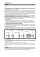
OPERATION Controls The hood is operated using the (5) push buttons located on the front edge of the hood. The Light switch turns the halogen lights on and off. Push the light switch once to turn the lights ON - push a second time to turn the lights ON to a brighter level push a third time to turn the lights OFF. The Glass switch turns the glass light on. Push the glass switch once to turn the glass light ON - push a second time to turn the light OFF.
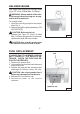
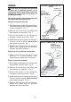
HALOGEN BULBS This range hood requires two halogen bulbs (Type T3, 12Volt, 20Watt Max, G-4 Base). WARNING: Always switch off the electrical supply before carrying out any operation on the appliance. To change bulbs: 1. Open the cover by prying from the proper slots. Fig. 2. 2. Remove the bulb by pulling sideways. (DO NOT ROTATE). ! CAUTION: Bulb may be hot. 3. Replace with Type T3, 12Volt, 20 Watt Max, G-4 Base halogen bulb. Do not touch replacement bulb with bare hands! ! FIG.
MAINTENANCE Proper maintenance of the Range Hood will assure proper performance of the unit. Grease Filter The grease filter should be cleaned frequently. Use a warm detergent solution. Grease filter is dishwasher safe. See “INSTALL FILTERS” section for removal and installation instructions. Hood Cleaning Stainless steel is one of the easiest materials to keep clean. Occasional care will help preserve its fine appearance. Cleaning tips: ● Hot water with soap or detergent is all that is usually needed.
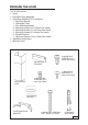
PREPARE THE HOOD Unpack hood and check contents. You should receive: 1 - Hood 1 - Decorative Flue Assembly 1 - Parts Bag (B080810747) containing: 1 - Mounting Bracket 1 - Discharge Collar 1 - Flue Mounting Bracket 8 - Mounting Screws (4.8 x 38mm Pan Head) 6 - Mounting Screws (3.9 x 9.5mm Pan Head) 2 - Mounting Screws (3.9 x 6mm Flat Head) 8 - Drywall Anchors 1 - Mounting Screws (2.9 x 9.5mm Pan Head) 1 - Installation Instructions 1 - Warranty Card 6 MOUNTING SCREWS (3.9 x 9.
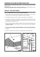
EXTERIOR OR INLINE BLOWER SELECTION CAUTION: To reduce the risk of fire and electric shock, install this rangehood only with EB6, EB9, EB12 or EB15 Exterior Blowers, or In-Line Blower model ILB3, ILB6, ILB9 or ILB11. The blower must be UL listed for Canadian and U.S. use, and evaluated for use with solid state speed control, rated 120V, 60 Hz, 6.0 A max. INSTALL THE DUCTWORK NOTE: To reduce the risk of fire, use only metal ductwork. 1. Choose the location where the exterior blower will be mounted.
WIRING ! CAUTION: All electrical wiring should be done by a qualified person (s) in accordance with all applicable codes and standards. This range hood must be properly grounded. BLOWER CONNECTION AT HOOD Exterior or In-Line blower CONNECT: WHITE-TO-WHITE, RED-TO-BLACK, GREEN-TO-GROUND. Do not turn power on at service panel until all wires have been connected. Blower connection at hood: 1. Run conductors (2-wire plus ground) from the blower to the hood’s wiring box marked “motor connection”. Fig. 7 2.
INSTALL MOUNTING BRACKET FRAMING BEHIND WOOD CROSS SUPPORT 1. Construct wood wall framing that is flush with interior surface of wall studs. Fig. 9. Make sure: a) the framing is centered over installation location. b) the height of the framing will allow the mounting bracket to be secured to the framing within the dimensions shown. 2. After wall surface is finished, secure the mounting bracket to framing with (2) 4.8 x 38mm mounting screws. See chart below for mounting bracket location.
INSTALL FLUE MOUNTING BRACKET FLUE MOUNTING BRACKET 3.9 x 6 mm FLAT HEAD BRACKET SCREWS 1. Assemble the flue mounting bracket, adjusting outside width as shown. Fig.10 2. Carefully center the mounting bracket directly over the range hood location. 3. Secure the bracket assembly to the ceiling using (2) 4.8x38mm mounting screws and drywall anchors (Fig. 11). Make sure the bracket is pushed into the corner, tight against the wall and centered over the hood. 9-13/16” (24.9 cm) FIG.10 DRYWALL ANCHORS 4.
INSTALL THE HOOD Note: On stainless steel hoods, carefully remove the plastic protective film from all exterior surfaces of the hood and decorative flues, prior to final installation. Note: at least two people will be required to mount the hood. 1. Raise the hood into its mounting position. 2. Align the rectangular opening on the back of the hood with the wall-mounting bracket. Gently lower the hood until it securely engages the bracket. Fig. 12. 3. Level the hood with (2) 3.9x9.
INSTALL THE HOOD, cont’d 7. Carefully place the decorative flue on the hood. Fig. 14. ROOMS WITH 10-FOOT CEILINGS Rooms with 10-foot ceilings require flue extension model AEWC26xB, available from your local dealer. 8. Discard the upper flue supplied with the product. Replace it with the flue extension. 9. Raise the upper flue until its holes align with holes in the flue mounting bracket (located on ceiling). Fig. 15. 10. Secure the flue with (2) 3.9x9.5mm mounting screws. Fig. 15. 11.
INSTALL FILTERS 1. To remove the GREASE filter, grip the latch tab and pull it down. This will disengage the filter from the hood. Tilt the filter downward and remove. Fig. 17. 2. To install the GREASE filter, align rear filter tabs with slots in the hood. Pull latch tab down, push filter into position and release. Make sure the filter is securely engaged after installation. Fig.17. NOTE: Prior to use, remove protective film from the filter frame. GREASE FILTER FIG.
LISEZ ET CONSERVEZ CES INSTRUCTIONS ! SEULEMENT POUR UTILISATION DOMESTIQUE ! AVERTISSEMENTS POUR REDUIRE LES RISQUES D’INCENDIE, DE DECHARGES ELECTRIQUES OU DE DOMMAGES AUX PERSONNES, OBSERVEZ LES INSTRUCTIONS SUIVANTES: 1. N’utilisez cet appareil que comme cela est indiqué par le constructeur. Si vous avez des problèmes, contactez le fabriquant à l’adresse ou au numéro de téléphone indiqués dans la garantie. 2.
4. Utilisez un extincteur SEULEMENT si: A. Vous savez que vous avez un extincteur Classe ABC, et vous en connaissez déjà le mode d’emploi. B. Ce n’est pas un très gros incendie et qu’il se limite à l’endroi où il a explosé. C. Vous êtes en train d’avertir les pompiers. D. Vous avez la possibilité d’essayer d’éteindre l’incendie en ayant le dos tourné vers une issue. * D’après les “Suggestions concernant la Sécurité contre les incendies des cuisines” publiées par NFPA. ! ATTENTION 1.
FONCTIONNEMENT Commandes La hotte fonctionne à l’aide de cinq (5) boutons-poussoirs situés sur le bord antérieur de votre hotte. Le Bouton de la lumière allume et éteint les lampes halogènes. En pressant 1 fois la touche, la lumière s’allume au 1er niveau; en pressant 2 fois la touche, la lumière du 2ème niveau s’allume (éclairage plus intense); en pressant encore une fois la touche, la lumière s’éteint. Le Bouton de la lumière du verre actionne la lumière du verre.
AMPOULES HALOGENES Ce modèle de hotte veut deux (2) ampoules halogènes (Type T3, 12Volt, 20 Watt Max, G4 Base). ATTENTION: avant de procéder à quelconque opération, débranchez l’appareil. Pour changer les ampoules: 1. Ouvrez le couvercle en faisant levier grâce aux fissures prévues à cet effet. Fig. 2. 2. Retirez l’ampoule en tirant latéralement. (NE LA FAITES PAS TOURNER). ATTENTION: l’ampoule peut être chaude! 3.
ENTRETIEN Un bon entretien de votre hotte garantira une excellente performance. Filtre anti-graisse Le filtre anti-graisse doit être nettoyé fréquemment. Utilisez une solution contenant un détergent tiède. Le filtre anti-graisse peut être lavé au lave-vaisselle. Voir la section “INSTALLER LES FILTRES” pour les instructions relatives au démontage et à l’installation. Nettoyage de votre hotte L’acier inoxydable est une des matières les plus faciles à nettoyer.
PREPAREZ LA HOTTE Enlever la hotte dans l’emballage et controller le contenu. Vous devez recevoir : 1 - Hotte 1 - Conduit décoratif 1 - Sachet (B080810747) avec: 1 - Étrier d’assemblage 1 - Collier d’évacuation 1 - Étrier de support 8 - Vis d’assemblage (4.8 x 38mm Tête ronde) 6 - Vis d’assemblage (3.9 x 9.5mm Tête ronde) 2 - Vis d’assemblage (3.9 x 6 mm Tête plate) 8 - Chevilles 1 - Vis d’assemblage (2.9 x 9.
SELECTION UNITE EXTERIEURE OU INLINE ATTENTION : pour diminuer les risques d’incendie ou de décharges électriques, installer cette hotte uniquement avec des unité extérieures modèle EB6, EB9, EB12 ou EB15, ou unité In-Line modèle ILB3, ILB6, ILB9 ou ILB11. Les unités doivent être compries dans la liste UL pour l’utilisation au Canada et aux USA et approuvée pour l’utilisation avec un “dispositif de contrôle de la vitesse” à l’état solide, dont les données sur la plaque sont 120V, 60 Hz, 6.0 A max.
INSTALLATION ELECTRIQUE ! ATTENTION:L’installation électrique doit être faite par du personnel qualifié selon les normes. Cette hotte de cuisinière doit être installée correctement. BRANCHEMENT DE LA TURBINE DE VENTILATION À LA HOTTE BRANCHER:LE BLANC AVEC LE BLANC, LE ROUGE AVEC LE NOIR ET LE VERT à LA TERRE Unité extérieure ou In-Line Ne pas faire fonctionner tant que tous les fils n’ont pas été branchés. Branchement de la turbine de ventilation à la hotte : 1.
INSTALLATION ETRIER D’ASSEMBLAGE CADRE DERRIÈRE L’APPUI TRANSVERSAL EN BOIS 1. Construisez un cadre en bois pour le mur dont les vis-pivot ne dépassent pas. Fig. 9. Assurez-vous: a) que le cadre est centré au-dessus de l’emplacement de l’installation. b) la hauteur du cadre permettra que l’étrier d’assemblage soit fixé au cadre en respectant les dimensions indiquées. 2. Après avoir complété la finition de la surface du mur, fixer l’etrier d’assemblage au cadre avec des vis de montage (2) de 4.8 x 38 mm.
INSTALLATION ETRIER DE SUPPORT DU CONDUIT DECORATIF ETRIER DE SUPPORT DU CONDUIT DECORATIF 3.9 x 6 mm VIS D’ASSEMBLAGE À TÊTE PLATE 1. Assemblez l’étrier de support du conduit décoratif en réglant la largeur extérieure comme indiqué. Fig. 10. 2. Centrez soigneusement le support directement sur l’emplacement destine à la hotte. 3. Fixez l’assemblage du support au plafond au moyen de deux (2) vis de montage de 4.8 x 38 mm et des chevilles (Fig. 11).
INSTALLATION DE LA HOTTE Remarque : si la hotte est en acier inoxydable, retirez précautionneusement le film protecteur des surfaces extérieures et du conduit décoratif avant de terminer l’installation. Remarque : la hotte doit être installée par au moins deux personnes. 1. Soulevez la hotte et placez-la à l’endroit où elle sera installée. 2. Alignez l’ouverture rectangulaire située à l’arrière de la hotte avec l’étrier d’assemblage.
INSTALLATION DE LA HOTTE, suite 7. Placez précautionneusement le conduit décoratif sur la hotte (Fig. 14). CONDUIT SUPÉRIEUR PIÈCES AVEC DES PLAFONDS DE 10’ Les pièces avec des plafonds de 10’ ont besoin d’un modèle d’extension de conduit AEWC26xB, disponible auprès de votre distributeur local. 8. Jetez le conduit supérieur fourni avec le produit. Remplacez-le par l’extension du conduit. 9.
INSTALLER LES FILTRES 1. Pour ôter le filtre ANTI-GRAISSE, saisir la languette de verrouillage et la tirer vers le bas. Le filtre se dégagera ainsi de la hotte. Le faire balancer vers le bas et le retirer. Fig. 17. 2. Pour installer le filtre ANTI-GRAISSE, aligner les languettes arrière du filtre sur les fentes dans la hotte. Tirer la languette de verrou, pousser le filtre en place et relâcher. S’assurer que le filtre est solidement engagé après l’installation. Fig.17. FILTRE A GRAISSE FIG.
LEA Y CONSERVE ESTAS INSTRUCCIONES ! INDICADO PARA EL USO EN COCINAS DOMESTICAS ! ADVERTENCIA PARA EVITAR EL RIESGO DE INCENDIO, CORTOCIRCUITO O DAÑO PARA LAS PERSONAS, OBSERVE ATENTAMENTE LAS SIGUIENTES NORMAS: 1. Use esta unidad solamente de la manera indicada por el fabricante; si tiene dudas, póngase en contacto con éste a la dirección o teléfono indicados en la garantía. 2. Antes de hacer una revisión o de limpiar la unidad, desconéctela de la red para evitar que se encienda de manera accidental.
! ADVERTENCIA 1. Para reducir el riesgo de incendios y para evacuar correctamente los humos, asegurarse de haber realizado una conducción del aire hasta el exterior. No expulsar los humos en espacios cerrados por paredes o techos, áticos, espacios angostos o garajes. 2. Prestar la máxima atención al utilizar productos de limpieza o detergentes. 3. Evitar el uso de productos alimentarios que puedan inflamarse bajo la campana. 4. Sólo para ventilación total.
FUNCIONAMIENTO Mandos La campana se opera mediante los 5 botones pulsadores que se encuentran en el frontal de la campana. El interruptor luz enciende y apaga las lámparas halógenas. Pulsando el botón una vez, la luz se enciende a intensidad 1, pulsándolo una segunda vez, la luz se enciende a intensidad 2 (luz más intensa) y, pulsándolo otra vez más, la luz se apaga completamente. El interruptor del cristal enciende la luz de cristal.
LAMPARAS HALOGENAS Este tipo de campana necesita dos (2) lámparas halógenas (Tipo T3, 12Volt, 20 Watt Max, G-4 Base). ATENCIÓN: antes de proceder a cualquier operación, es necesario desconectar el aparato. Para cambiar las lámparas: 1. Abra la tapa haciendo palanca sobre las hendiduras apropiadas. Fig. 2. 2. Quite la bombilla tirando de los lados. (NO LA GIRE). ! ATENCIÓN: las lámparas pueden estar calientes. 3. Sustituir con lámparas del mismo tipo (T3, 12Volt, 20 Watt Max, G-4 Base).
MANTENIMIENTO Un mantenimiento adecuado de la campana asegura el funcionamiento correcto del aparato. Filtro antigrasa El filtro antigrasa debe limpiarse con frecuencia. Use un detergente que no sea fuerte.Use un detergente que no sea fuerte. El filtro antigrasa se puede meter en el lavavajillas. Las instrucciones de desmontaje e instalación se encuentran en la sección “INSTALACIÓN DE LOS FILTROS”.
PREPARE LA CAMPANA Sacar la campana de l’embalaje y controlar el contenido. Recivireis: 1 - Campana 1 - Tubo decorativo 1 - Bolsita (B080810747) con: 1 - Soporte de montaje 1 - Casquillo 1 - Soporte para el montaje del tubo 8 - Tornillos de montaje (4.8x38mm cabeza redonda) 6 - Tornillos de montaje (3.9x9.5mm cabeza redonda) 2 - Tornillos de montaje (3.9x6 mm cabeza plano) 8 - Escarpias 1 - Tornillos de montaje (2.9x9.
SELECCIÓN DE LA CENTRALITA EXTERNA O INLINE ATENCIÓN: para reducir el riesgo de incendio o de descargas eléctricas, instale esta campana sólo con centralita externa mod. EB6, EB9, EB12 o EB15, o centralita In-Line mod. ILB3, ILB6, ILB9 o ILB11. La centralita tiene que estar incluida en la lista UL para el uso en Canadá y USA y tiene que ser evaluada la utilización con “dispositivo de control de la velocidad” en el estado sólido y los datos de su placa son 120 V, 60 Hz, 6.0 A máx.
INSTALACION ELECTRICA ! PRECAUCIÓN : Toda la instalación eléctrica tiene que ser realizada exclusivamente por personal preparado y a norma con los estándares y las reglas establecidas. Esta campana tiene que ser instalada correctamente. CONEXIÓN DEL VENTILADOR A LA CAMPANA Centralita CONECTE: externa o EL CABLO BLANCO In-Line CON EL BLANCO, EL ROJO CON EL NEGRO Y EL VERDE A LA TOMA DE TIERRA No encienda la campana hasta que todos los cables estén instalados. Conexión del ventilador a la campana: 1.
INSTALACION SOPORTE DE MONTAJE MARCO POSTERIOR DEL APOYO TRANVERSAL DE MADERA 1. Construya una estructura de madera en la pared que quedará nivelada con la parte interior de los tacos en la pared. Fig.9. Asegúrese de que: a) La estructura se encuentra centrada por encima de la instalación del tubo. b) La altura de la estructura permite fijar el soporte de montaje en esta estructura siguiendo las dimensiones indicadas. 2.
INSTALACIÓN DEL SOPORTE PARA EL MONTAJE DEL TUBO SOPORTE PARA EL MONTAJE DEL TUBO TORNILLOS DE MONTAJE DE CABEZA PLANA DE 3.9 x 6 mm 1. Ensamble el soporte para el montaje del tubo, ajustando el ancho exterior tal como se muestra. Fig. 10. 2. Centre cuidadosamente el soporte para el montaje del tubo directamente sobre la ubicación de la campana de la cocina. 3. Asegure el soporte al techo utilizando (2) tornillos de montaje de 4.8 x 38 mm y escarpias (Fig. 11).
INSTALACIÓN DE LA CAMPANA Nota: En campanas de acero inoxidable, antes de llevar a cabo la instalación final, retire cuidadosamente la película protectora de plástico de todas las superficies exteriores de la campana y del tubo decorativo. Nota: se necesitan al menos dos personas para montar la campana. 1. Levante la campana en su posición de montaje. 2. Alinee la abertura rectangular de la par te posterior de la campana con el soporte de montaje de la pared.
INSTALACIÓN DE LA CAMPANA, (cont) TUBO DECORATIVO SUPERIOR 7. Coloque con cuidado la chimenea decorativa sobre la campana. Fig. 14. SALAS CON TECHOS DE 10 PIES Las salas con techos de 10 pies precisan la extensión del tubo modelo AEWC26xB, disponibles en su distribuidor local. 8. Deseche el tubo superior suministrado con el producto. Sustitúyalo por la extensión del tubo. 9. Levante el tubo superior hasta que sus orificios queden alineados con el soporte para el montaje del tubo (situado en el techo).
INSTALACIÓN DE LOS FILTROS 1. Para desmontar el filtro ANTIGRASA, agarre la pestaña del cierre y tire hacia abajo. Así se soltará el filtro de la campana. Incline el filtro hacia abajo y retírelo. Fig. 17. 2. Para instalar el filtro ANTIGRASA, alinee las pestañas traseras del filtro con las ranuras de la campana. Tire hacia abajo de la pestaña de cierre, empuje el filtro a su posición y suéltela. Una vez colocado, compruebe que el filtro queda bien engranado. Fig.17. FILTRO ANTIGRASA FIG.
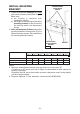
SERVICE PARTS MODEL WC26E KEY NO. PART NO.
LISTE PIECES DE RECHANGE MODELE WC26E KEY NO. PART NO.
LISTA DE PIEZAS DE RECAMBIO MODELO WC26E KEY NO. PART NO.
SERVICE PARTS - LISTE PIECES DE RECHANGE LISTA DE PIEZAS DE RECAMBIO MODEL WC26E 04307488/2