MODELS BestStand 400 Series BestStand 500 Series BestStand 600 Series SIT-TO-STANDLIFT Ensure the product has been assembled according to the instructions in this manual. All operators should have received or read and understood the instructions for safe and proper operation of the patient lift.
Thank you for choosing Bestcare! To better serve you, please record the following information: Supplier Name: Telephone: Serial #: Date of Purchase: INSPECT YOUR MERCHANDISE Upon receipt of your Bestcare Lift, verify that all merchandise is complete and free from any shipping damage. Refuse delivery if the packaging appears to be badly damaged. If the merchandise is received damaged or is missing components, contact the shipping company immediately and file a claim.
Norcross, GA 30071 678-679-6690 / 1-877-8229033 www.bestcarellc.com © 2013 Bestcare LLC REV. 052213 SAFETY INSTRUCTIONS The BestStand Sit-To-Stand patient lift allows a caregiver to lift and transfer a patient safely with minimum physical effort. Before attempting to lift anyone, you should practice operating the lift and be able to explain to the patient the lifting and transfer procedures. Arrange all necessary items (e.g. lift, sling, commode chair or wheelchair) properly for a smooth transfer.
• While the patient is suspended, always keep the patients centered between the base legs. • Do not attempt to roll the lift or casters over floor obstacles while the user is in the sling and on board. • Use only Bestcare slings specially designed and tested for Bestcare patient lifts . Do not use slings manufactured by other companies on Bestcare sit-to-stand patient lift. Bestcare LLC is not responsible for any consequence resulting from using non-Bestcare products.
Symbols used in this manual and their meanings: Warning! Failure to heed this warning may result in damage to the product or serious injury to the operator and/or user. Important instructions follow. Read and understand the instructions in the manual before using the product. Note! Important information concerning the product and/or its correct and proper usage follows.
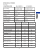
SPECIFICATIONS & OPTIONS CONTROL BOX EL SERIES E SERIES Input Voltage 220-240VAC 50Hz / 110-120VAC 60Hz 220-240VAC 50Hz / 110-120VAC 60Hz Output Voltage 24 VDC 24 VDC Battery Pack 24 VDC 5AH 24 VDC 5AH Control Handset Panel and Handset Protection Class IPxx IP66 Over-duty alarm by buzzer by LCD Battery Status by LED color indicator by LCD SA400 series SA500 series SA600 series 400 Lb. 500 Lb. 600 Lb. Max. height of Boom 68” 68” 68” Min.
Dual Front Casters No Yes Yes *Bestcare is committed to continuous improvements of our products, therefore the specs, dimensions and features listed above are for guidance only and subject to change without prior notice.
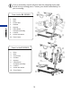
Prior to assembly, unpack all parts from the shipping carton and check for any missing parts. Contact your dealer immediately if a part is missing. Parts List for EL SERIES 1. 2. 3. 4. 5. 6. 7 8 9. 10 Base Mast Control Box Pendant Actuator Lifting Boom Kneepad Assembly Footrest Castor with Brake Front Castor Parts List for E SERIES 1. 2. 3. 4. 5. 6. 7 8 9.
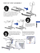
STEP BY STEP ASSEMBLY 1 Engage the brakes. Remove the bolts from the bottom of the mast and base. Pull the mast to an upright position. Re-insert the bolts into the holes at bottom of the mast and tighten the nuts. 2 Attach boom to top of mast. Re-insert the bolts into the holes at bottom of the mast and tighten the nuts. 3 A. Attach the bottom actuator to the bracket on the mast and insert pin. Insert keeper ring through hole in pin to secure base of actuator. B.
KNEEPAD ASSEMBLY A. Insert slotted bolt through bracket with washer on the outside and loosely attach threaded knob to the mast by turning the knob two times. B. Slide “L” arm inside bracket with slotted bolt head inside the “L” arm then tighten to secure. Repeat these steps for the other side. C. With both “L” to the mast, slide the kneepad onto the “L” arms and fasten into place with “U” bracket and knob bolt.
CONTROL BOX INSTALLATION FOR PERFORMANCE SERIES (for LEGACY electronic assembly see page 15) Install the control box. Slide the control box over and onto the flat metal hook mounted at the bottom of the mast. Line up the control box with the hole at the top of the mast and insert the screw to hold the control box in place.
Battery Volume Overused low battery 50% 50% Battery Capacity Remaining Charge batteries immediately. 25% 25% Battery Capacity Remaining Charge batteries immediately. 10% Battery is charged to around 10% Buzzer beeps / Only lowering possible 0% Power off Battery Low (Blink) EMERGENCY STOP PERFORMANCE ELECTRONICS ONLY Emergency stop button interrupts the power supply to the actuators and makes the actuators stop immediately in case of sudden FOR danger.
Step 1: Install two mounting bolts (M5 or gauge 10 having at least 8mm head) onto the mounting surface that are 12.4 in. / 31.6cm apart as shown in Fig. A. Step 2: Turn the lock mechanism to the unlocked position Fig.B. Step 3A: Hook the charging unit onto the mounting surface by first sliding the bottom slot over the bottom screw. Step 3B: Align and fasten the top hole to the top screw. *you may have to adjust the bolts for a tight and flush fit with the mounting surface.
PATIENT LIFT WILL NOT OPERATE WHILE CHARGING CHARGING THE BATTERY • • • • • • • Ensure the power is switched “ON” (the red “RESET” button should be up). Insert charging plug into charging port on the control box. Plug charger to power supply. All lights of battery indicator should be “ON” while charging. It takes approximately 2-3 hours to fully charge the batteries from one green light. It takes approximately 7-9 hours to fully charge the batteries from the red light.
• Push lift to charging location and charge the batteries with the charger provided. Avoid unpluging the hand control and motor from control box. Frequent plug/unplug of the hand control and motor into/from the control box may damage the control box. • Do not charge batteries over 12 hours. Double check all assemblies for tightness and read operating instructions carefully prior to use.
FITTING STAND ASSIST SLING • • • • • • • • • • Position the patient in a sitting position Slide the sling down patient’s back to lumbar position. Draw the shoulder straps to the front of the patient close to the chest. Draw the waist belt around patient’s waist and press together to fasten. buckle (adjust for comfort). Cross the short black strap over and pull the left loop strap through the black strap.
• • • Notice, in Diagram 2, that the Buttock strap MUST be used with the Stand Assist sling. These slings are designed to compliment one another in providing the greatest comfort and security for the patient being transferred. Push lift towards patient. Open the base of the lift. Apply the brakes in both rear casters. Proceed with lift and transfer as in Diagram 3.
• • • • • • • Release the brakes, close the base, and pull the lift away from the bed. Lower the patient to the object intended. To lift patient in a standing position, continue to lift until the patient’s knees are locked in a standing position. At the standing position, patient’s knees may move away from the knee pad. Release the brakes, close the base, and pull the lift away from the bed. Lower the patient to the object intended.
The BestCare Toileting Sling can be used with the BestStand to lift a patient in a sitting position. When in use the BestStand Toileting Sling supports the client under the thighs and across the mid-back area. Fitting the BestCare Toileting Sling • • • • • • • Slide the sling down patient’s back to lumbar position. Draw shoulder straps under the arms and around the chest into the front. Draw Velcro waist belt around waist and press together to fasten. Draw each leg support under the thigh.
Check connections between Boom and Mast for improper connection, looseness or wear. Check the Boom for bending and deflection. MAST Check the Mast for bending or deflection. BASE & FOOT PEDAL Check bolts and nuts for looseness. Check casters and axle bolts for tightness. Check rubber parts on the casters for deflection FIRST RECEIVED BASE & FOOT PEDAL Apply grease to caster ball bearings if needed. Check welding joints for rust and crack.
TROUBLESHOOTING GUIDE The following list of encountered problems and solutions will assist you in determining what may be causing your patient lift not to function as designed. If you have a problem occurring which is not listed below, please contact your dealer or technical support for help. Do not attempt to repair or replace components or parts on your lift as this may void your warranty or cause further problems that may result in patient injury.
EMERGENCY LOWERING MECHANISM The following instructions apply to BestStand 500 & 600 series ONLY In case there is a failure with the actuator or electronics and the user is left suspended in mid-air, please follow the procedures below to safely lower the user to a safer position. The Emergency Lowering Device is located at the top of the actuator shaft. It is intended for use if the actuator fail to operate while a patient is suspended.
Bestcare LLC warrants the following products and components for the time period specified: • • • • • • • • Lift frames and spreader bar: 3 years Actuator: 2 years Parts including casters, control box, PCB, pendant, charger: 2 years Batteries: 1 year Weigh Scale: 2 years Spryte Stand Aid all components: 2 years Hydraulic pumps: 1 year Reusable slings: 6 months Bestcare LLC Single Patient Slings are designed for limited use with one patient and may not be washed.
Bestcare LLC 2920 Pacific Drive Norcross, GA 30071 tel. 678-679-6690 free 1-877-8229033 www.bestcarellc.