Nederlands Gebruikershandleiding plafondventilator (120cm) Deutsch Gebrauchsanweisung deckenventilator (120cm) Français Ventilateur de plafond (120cm), mode d'emploi English User's instructions, Ceiling fan 48" Italiano Ventilatore a soffitto (120cm) - Istruzioni per l'uso v 101119-07 DT48C
Gebruikershandleiding Veiligheidsvoorschriften - Algemeen • Lees de gebruiksaanwijzing goed door en bewaar deze zorgvuldig. • Gebruik dit apparaat alleen zoals beschreven in deze gebruiksaanwijzing.
Gebruikershandleiding werking - Algemeen Nederlands 1 6 4 2 1. 2. 3. 4. 5. 6. 3 Montageplaat Neerwaartse stang Motor Blad 5 Bladhouder Sierkap Figuur 1 montage - Het installeren van de ventilator • Zorg dat u de ventilator hangt op een plaats waar de afstand tussen ventilatorbladen en de vloer tenminste 2,30m zal zijn. • Bevestig de wandcontactdoos aan het plafond of de gebruikte bestaande doos.
Gebruikershandleiding Stang Geel/Groen Sierkap Geel/Groen Geel/Groen Blauw Blauw Bruin Zwart Geel/Groen Montage Plaat Aarde Nul Fase N L Zwart Motor 7. Monteer de geel-groene draad, die van de motor komt, aan de aardeschroef op de binnenkant in de sierkap (Zie figuur 4). Figuur 4 8. Monteer de geel-groene draad, die aan de stang zit, ook aan de schroef op de binnenkant in de sierkap (Zie figuur 4). 9. Steek nu de bladen in de daarvoor bestemde sleuven en schroef ze vast.
Gebruikershandleiding A Nederlands Figuur 6 aansluiting B connectoren A en B 11. Zet de afdekkap met 4 schroeven vast aan de motor. Niet alle schroeven zitten evenwijdig (Zie figuur 7). Figuur 7 Schakel nu eerst de stroom van de betreffende ruimte uit. Dit doet u het beste door de zekering in de meterkast los te draaien en of uit te schakelen. Controleer daarna of de stroom inderdaad echt uitgeschakeld is! 12.
Gebruikershandleiding Gebruik de aansluiting N op de rechterzijde van het blokje. Dat is de zijde die het dichtst bij de middenopening zit. 15. Sluit de bruine draad, die uit het plafond komt, aan op het aansluitblokje van de montageplaat. Gebruik de aansluiting L op de rechterzijde van het blokje. Dat is de zijde die het dichtst bij de middenopening zit. 16. Hang de compleet gemonteerde ventilator met de sierkap aan de J-haak die onder aan de montageplaat zit.
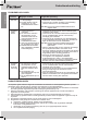
Gebruikershandleiding Problemen oplossen Nederlands Probleem Mogelijke oorzaak Aangeraden oplossing 1. V entilator start niet 1. S top of circuitonderbreker is doorgeslagen. 2. E r zitten draden naar de ventilator los, of in de schakelkast zitten draden los. 1. Controleer de stoppen of circuitonderbrekers voor het hoofdcircuit of de circuittakken. 2. Controleer of er draden los zitten in de bedrading naar de ventilator en in de schakelkast. 2. Ventilator maakt lawaai 1.
e. een reparatie die is uitgevoerd door derden; f. een onzorgvuldige transportwijze zonder geschikte verpakking respectievelijk bescherming. 7. Op deze garantiebepalingen zal geen aanspraak gemaakt kunnen worden bij: a. verliezen die zich tijdens het transport voordoen; b. het verwijderen of wijzigen van het serienummer van het apparaat. 8. Uitgezonderd van garantie zijn snoeren, lampen en glazen onderdelen. 9.
Gebrauchsanweisung Wir gratulieren Ihnen zum Kauf dieses Deckenventilator. Sicherheitsbestimmungen - Allgemein • Lesen Sie sich diese Bedienungsanleitung aufmerksam durch und bewahren Sie sie sorgfältig auf. • Verwenden Sie das Gerät nur wie in dieser Bedienungsanleitung beschrieben.
Gebrauchsanweisung funktion - Allgemein 1 6 4 1. 2. 3. 4. 5. 6. 3 Montageplatte Stab Motor Flügel 5 Flügelhalter Kappe Deutsch 2 Abbildung 1 Montage - Installieren der Ventilator • Seien Sie sicher, dass der Lüfter hängt an einem Platz, wo der Abstand zwischen den Lüfterflügel und der Fußboden mindestens 2,30m sein wird. • Montieren Sie die Ausgangsdose an der Decke, oder verwenden Sie die vorhandene Dose.
Gebrauchsanweisung montage - Anschließen Stab Gelb/Grün Kappe Gelb/Grün Gelb/Grün Blau Blau Braun Schwarz Gelb/Grün Montage Platte Erde Null Phase N L Deutsch Schwarz Motor 7. Montieren Sie den gelb-grünen Draht, der aus dem Motor kommt auf die Erde Schraube auf der Innenseite in der Abdeckung. (Siehe Abbildung 4) Abbildung 4 8. Montieren Sie den gelb-grünen Draht, der an dem Stab sitzt, auch an die Erde-Schraube auf der Innenseite in der Abdeckung. (Siehe Abbildung 4) 9.
Gebrauchsanweisung Abbildung 6 anschließen die B Steckverbinder A und B 11. Befestigen Sie die Abdeckkappe mit 4 Schrauben am Motor. Nicht alle Schrauben sind parallel positioniert. (Siehe Abbildung 7.) Abbildung 7 Schalten Sie zuerst den Strom des betreffenden Raums aus. Zu diesem Zweck können Sie am besten die Sicherung im Sicherungskasten herausdrehen oder ausschalten. Prüfen Sie danach, ob der Strom auch wirklich ausgeschaltet ist! 12.
Gebrauchsanweisung 14. Schließen Sie den blauen Draht, der aus der Decke herausragt, an die Anschlussleiste der Montageplatte an. Verwenden Sie den Anschluss N auf der rechten Seite der Anschlussleiste. Das ist die Seite, die der Mittenöffnung am nächsten ist. 15. Schließen Sie den braunen Draht, der aus der Decke herausragt, an die Anschlussleiste der Montageplatte an. Verwenden Sie den Anschluss L auf der rechten Seite der Anschlussleiste. Das ist die Seite, die der Mittenöffnung am nächsten ist.
Gebrauchsanweisung Fehlerbehebung Problem Wahrscheinliche Ursache Empfohlene Maßnahme zur Behebung 1. V entilator dreht sich nicht 1. S icherung oder Leistungsschalter durchgebrannt. 2. S tromleitungsverbindung zum Ventilator lose, oder lose Anschlüsse der Schaltungsdrähte im Schaltergehäuse. 1. Prüfen Sie die Sicherungen oder Leistungsschalter der Haupt- bzw. Abzweigschaltung. 2.
Gebrauchsanweisung Deutsch b. falsche Montage und/oder Benutzung, die gegen die einschlägigen gesetzlichen und technischen Normen oder gegen Sicherheitsnormen verstößt c. Anschluss an eine andere Netzspannung als die auf dem Typenschild angegebene d. eine ungenehmigte Veränderung e. eine Reparatur, die durch Dritte ausgeführt wurde f. nachlässigen Transport ohne geeignete Verpackung bzw. ohne geeigneten Schutz 7. Auf diese Garantiebestimmungen kann kein Anspruch erhoben werden im Falle von: a.
Mode d’emploi Nous vous félicitons de votre achat! Consignes de sécurité - Généralités • Lisez soigneusement le mode d’emploi et conservez-le précieusement. • Utilisez cet appareil uniquement suivant les instructions décrites dans le mode d’emploi.
Mode d’emploi Fonctionnement - Généralités 1 6 4 2 3 1. Plaque de montage 2. Tige descendante 3. Moteur 4. Pale 5 5. Support de pale (1 par pale) 6. Couvercle de protection Figure 1 Montage - Installer le ventilateur Français • S’assurer que le ventilateur se bloque à un endroit où la distance entre les pales du ventilateur et la parole sera donnée au moins 2,30m. • Installez la boîte de prise de courant au plafond ou utilisez la boîte existante.
Mode d’emploi montage - Connexion Tige Jaune/Vert Cache Jaune/Vert Jaune/Vert Bleu Jaune/Vert Plaque de montage Terre Nulle Phase Bleu Brun Noir N L Noir Moteur Français 7. Fixez le fil jaune et vert sortant du moteur sur la face intérieure du cache à l’aide de la vis de terre. (voir figure 4) Figure 4 8. Fixez également le fil jaune et vert fixé à la barre sur la face intérieure du cache à l’aide de la vis. (voir figure 4) 9. Desserrez les trois vis.
Mode d’emploi A Figure 6 raccordement des B connecteurs A et B 11. Fixez le capot sur le moteur à l’aide de 4 vis. Toutes les vis ne sont pas parallèles (voir figure 7). Français Figure 7 Avant toute chose, coupez le courant dans la pièce concernée. Pour ce faire, le mieux est de couper ou de retirer le fusible dans l’armoire électrique. Assurez-vous ensuite que le courant est bel et bien coupé ! 12. Montez la plaque de montage au plafond ou contre une prise au plafond.
Mode d’emploi 14. Raccordez le fil bleu sortant du plafond sur le bornier de la plaque de montage. Utilisez la borne N située sur le côté droit du bornier. Il s’agit du côté situé le plus près de l’ouverture centrale. 15. Raccordez le fil brun sortant du plafond sur le bornier de la plaque de montage. Utilisez la borne L située sur le côté droit du bornier. Il s’agit du côté situé le plus près de l’ouverture centrale. 16.
Mode d’emploi Solutions aux problèmes Cause possible Solution possible 1. L e ventilateur ne se met pas en marche 1. Fusible ou disjoncteur grillé 2. F ils électriques du ventilateur desserrés ou fils de l’interrupteur desserrés dans le boîtier d’interrupteur. 1. Vérifiez les fusibles de circuit principal et de dérivation ou les disjoncteurs. 2. Vérifiez les fils électriques du ventilateur et les fils d’interrupteur dans le boîtier d’interrupteur. 2. L e ventilateur est bruyant 1.
Mode d’emploi 7. Les présentes conditions de garantie ne peuvent pas être invoquées dans les cas suivants: a. pertes survenues pendant le transport; b. effacement ou modification du numéro de série de l’appareil. 8. Les cordons, ampoules et pièces en verre ne sont pas couverts par la garantie. 9. La garantie ne donne aucun droit d’indemnisation pour des dommages éventuels, autres que le remplacement ou la réparation de pièces défectueuses.
User’s instructions Congratulations with the purchase of this ceiling fan. Safety instructions - General • Please read these instructions carefully, and retain them for future reference. • Use this appliance solely in accordance with these instructions.
User’s instructions operation - General 1 6 4 2 3 1. Mounting Plate 2. Down rod 3. Motor 4. Blade 5 5. Blade holder 6. Canopy Figure 1 montage - Installing the fan • Be sure to hang the fan in a place where the distance between the fan blades and the floor will be at least 2.30m. • Mount the outlet box to the ceiling or used existing box. In order to ensure proper support, use two wood screws, to secure the outlet box to a joist or beam.
User’s instructions Montage - Connection Down rod Yellow/Green Canopy Yellow/Green Yellow/Green Blue Blue Brown Black Yellow/ Green Earth Neutral Line Mounting Plate N L Black Motor 7. Connect the yellow-green wire, which comes from the motor, to the earth screw on the inside of the canopy (See figure 4). Figure 4 English 8. Connect the yellow-green wire, which comes from the rod, also to the earth screw on the inside of the canopy (See figure 4). 9. Remove the 3 screws.
User’s instructions A Figure 6 B connectors A and B 11. Mount the cover with 4 screws to the motor. Not all screws are parallel. (See Figure 7) First switch off the power in the room you are working in. Preferably removing the fuse or switch off. Now check whether the power is really off! 12. Mount the mounting plate to the ceiling or to the ceiling outlet. Preferably with 4 solid screws distributed over the 4 slotted holes in the mounting plate (See Figure 8).
User’s instructions 14. Connect the blue wire, which comes from the ceiling, to the terminal block of the mounting plate. Use the connection “N” on the right side of the block. That is the side closest to the hole. 15. Connect the brown wire, which comes from the ceiling, to the terminal block of the mounting plate. Use the connection “L” on the right side of the block. That is the side closest to the hole. 16. Hang the fan fully assembled with the canopy to the J-hook under the mounting plate.
User’s instructions Troubleshooting Trouble Prabable Cause Suggested Remedy Fan will not start 1. Fuse or circuit breaker blown. 2. L oose power line connections to the fan, or loose switch wire connections in the switch housing. 1. Check main and branch circuit fuses or circuit breakers. 2. Check line wire connections to fan and switch wire connections in switch housing. Fan sounds noisy 1. Loose screws in motor housing. 2. S crews securing fan blade flanges to motor hub are loose. 3.
User’s instructions other consequences, resulting either directly or indirectly from the appliance supplied by the importer. 10. In case of claims under guarantee you can contact your dealer where the appliance is purchased. Bestron offers you also the possibility to send the appliance directly to our Service Department. Do not send your appliance without consulting us. The package may be refused and any any costs will be for your account.
Istruzioni per l’uso Congratulazioni per l’acquisto di questa ventilatore a soffitto. Prescrizioni di sicurezza - Generalità • Leggere attentamente le presenti istruzioni per l’uso e conservarle con cura. • Utilizzare l’apparecchio esclusivamente secondo le modalità descritte nelle presenti istruzioni.
Istruzioni per l’uso Funzionamento - Avvertenze generali 1 6 4 2 3 1. Piastra di montaggio 2. Stelo 3. Motore 4. Pala 5 5. Supporto della pala 6. Calotta Figura 1 Montaggio - Installazione del ventilatore • Assicurarsi che la ventola si blocca in un luogo dove la distanza tra le pale del ventilatore e il pavimento sarà di almeno 2.30. • Montare la scatola di connessione al soffitto oppure utilizzare la scatola presente.
Istruzioni per l’uso Montaggio - Connessione Asta Giallo/Verde Calotta Giallo/Verde Giallo/Verde Blu Blu Marrone Nero Giallo/ Verde Terra Neutro Fase Piastra di Sostegno N L Nero Motore 7. Montare il filo giallo-verde, proveniente dal motore, alla vite di terra nella parte interna della calotta decorativa. (Vedi figura 4) Figura 4 Italiano 8. Montare anche il filo giallo-verde, che è fissato all’asta, alla vite nella parte interna della calotta decorativa. (Vedi figura 4) 9.
Istruzioni per l’uso A Figura 6 collegamento connettori B AeB 11. Fissare la calotta di protezione al motore con 4 viti. Non tutte le viti si trovano parallele (Vedi figura 7). Figura 7 Per prima cosa staccare la corrente nel locale dove si sta montando il ventilatore. Per fare ciò è preferibile svitare il fusibile nel contatore e disinserirlo. Quindi controllare che la corrente sia effettivamente disinserita! 12.
Istruzioni per l’uso 14. Collegare il filo blu, proveniente dal soffitto, al blocchetto di collegamento della piastra di sostegno. Utilizzare il collegamento N alla destra del blocchetto. Si tratta del lato che si trova più vicino all’apertura centrale. 15. Collegare il filo marrone, proveniente dal soffitto, al blocchetto di collegamento della piastra di sostegno. Utilizzare il collegamento L alla destra del blocchetto. Si tratta del lato che si trova più vicino all’apertura centrale. 16.
Istruzioni per l’uso Eliminazione dei guasti Problema Probabile causa Rimedi consigliati 1. I l ventilatore non gira 1. Fusibile o interruttore di potenza bruciato. 2. Collegamento del conduttore elettrico al ventilatore allentato oppure terminali dei fili degli interruttori allentati nella scatola degli interruttori. 1. Controllare i fusibili o l’interruttore di potenza del circuito generale o di derivazione. 2.
Istruzioni per l’uso b. erronea installazione e/o utilizzo in contrasto con le disposizioni normative, tecniche o di sicurezza vigenti; c. collegamento del prodotto a una tensione di rete diversa da quella indicata nella targhetta di identificazione; d. modifiche non autorizzate; e. riparazioni eseguite da terzi; f. trasporto eseguito in modo improprio privo dell’imballaggio o delle protezioni idonee. 7. Le presenti condizioni di garanzia non si applicano inoltre in caso di: a.
DT48C v 101119-07