WORKSHOP MANUAL www.betamotor.
Foreword 2 3.6.2 Mounting the start-up device 33 1 Removing the engine from the vehicle 4 3.7 Primary gear and clutch unit 34 1.1 Exhaust manifold 5 3.7.1 35 1.2 Engine protection plat 5 Testing the clutch bell and replacing the silent-block 1.3 Transmission oil plug 5 3.7.2 Testing the clutch discs 36 1.4 Water cooling radiator 6 3.7.3 Testing the springs 37 1.5 Flywheel casing, clutch actuator and pinion 8 3.7.4 Testing the clutch drum 37 1.
Foreword www.betamotor.com Foreword This manual has been drafted for the motorcycle user and Technical Support operator, whereby it provides understandable information pertaining to the necessary operations of engine inspection, maintenance and repair. This manual must be thoroughly read before operating the engine. Engine life is prolonged by having a good knowledge of all the components and all the procedures to be followed when carrying out inspection and maintenance operations.
• Coolant contains hazardous substances that are Coolant harmful to the environment. When replacing the coolant you must have the right equipment for its disposal, in compliance with applicable regulations. • In certain situations, the ethylene glycol contai- ned in the coolant is flammable and its flame is invisible. Should the ethylene glycol ignite, even though its flame is invisible, it will cause burns. • Prevent the coolant from coming into contact • Do not dispose of coolant in the environment.
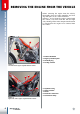
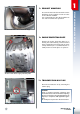
Removing the engine from the vehicle Removing the engine from the vehicle 1 Before removing the engine from the vehicle, thoroughly clean the entire motorbike and let it dry, then place it on a stable kickstand. Pictures 1 and 2 show the engine coupled with the vehicle, seen from both the left and right side, showing all the main components that must be removed for the engine to be removed from the vehicle.
Unscrew the two bolts that fasten the manifold flange to the cylinder in order to remove the exhaust manifold. It is recommended to turn the handlebar to one side to facilitate the operation. The two bolts of the exhaust manifold flange. 1.2 Engine protection plate Remove the engine protection plate by removing the four fastening screws from the frame. Should the protection plate be particularly deformed, it is recommended to carefully beat it back into place or replace it.
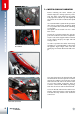
Removing the engine from the vehicle 1 1 .4 Water cooling radiator Before removing the water radiator you should empty the cooling system by removing the drain screw found on the pump body. Open the radiator cap and slightly tilt the vehicle to the left to facilitate the liquid flow. It is recommended to perform this operation after having removed the protection plate so as to prevent the coolant from remaining on the plate. The liquid can be reused if it has a clear blue colour. Liquid drain plug.
D B C A Disassembling the radiator. Unscrew the lower pin A, the four upper screws B (two on each side) and loosen the two clamps C (one on each side) that connect the radiator to the engine. Slightly turn the radiator forward and remove its two water pipes, simultaneously. Lower the radiator in such a way that the upper pin D comes out of its housing. 1 Removing the engine from the vehicle 1 .4 D Complete radiator: the upper pin (D) is highlighted.
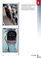
Removing the engine from the vehicle 1 1.5 Flywheel casing, clutch actuator and pinion Loosen the three screws that fasten the flywheel casing to the engine. This will let you access the clutch actuator, which is removed from the engine by loosening the four screws indicated. Remove the pinion by removing the specific Seeger ring. The three screws of the flywheel casing. The four screws of the clutch actuator. 1.
1 .7 Carburettor clamp 1 A B Removing the carburettor from the engine. A B Quadripole and monopole connector. In order to remove the carburettor from the engine you must loosen the two flaps A and B that fold around the intake collector 1 and sleeve 2 respectively, which connect it to the filter box. Then pull the carburettor towards the back part of the vehicle until it is released from its housing inside the container. 1.
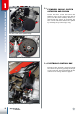
1 Removing the engine from the vehicle D B A C Engine bolts: A) swing arm bolt; B) upper bolt; C) lower bolt; D) bracket bolts. 1.9 Engine bolts A Swing arm bolt not being removed completely. The engine is fastened to the frame by four bolts: one at the front, one at the bottom, one at the top and one at the back. The description of the first of these four bolts being removed is found in paragraph 1.4, removal of the radiator.
Fasten the engine onto a solid and safe support so as to work with ease and safely. Then proceed as follows. 1 5 2 2.1 Thermal unit 6 3 The thermal unit consists of the external cap 1, the combustion chamber 2, the cylinder 3 and the piston 4. Assembly is completed with the O-ring 5, the seal head 6, the casing-cylinder seal 7 and the seven copper washers with the respective special screws M7x31. The description of these parts being disassembled is found further on.
2 3 Disassembling the engine 1 5 4 6 2 Head assembly. 1) 2) 3) 4) 5) 6) 12 External cap. Combustion chamber. Seal head. O-ring. Screws. Copper washers 7x12x0.5 2 .1.1 Head Once the water circuit is emptied, it is recommended to blow compressed air into the sleeve connected to the head in order to be sure there is no fluid in the thermal unit. Once the water sleeve is disconnected, loosen the spark plug, then the seven screws that fasten the external cap to the cylinder.
Remove the rubber tube that connects the cylinder to the water pump after having loosened the clamp; turn the motor shaft until the piston lies in the top dead centre and loosen the four bolts A that fasten the cylinder to the base unit. Then gently remove the cylinder by pulling it upwards. Note: Should the cylinder be stuck to the base unit, gently strike the cylinder in various points with a rubber mallet. A Disassembling the cylinder. Disassembling the engine 2 .1.2 Cylinder 2 2.1.
Disassembling the engine 2 A 2 .2 Intake system The intake system consists of the intake manifold B and the lamella pack C. To disassemble this, remove the four screws A that fasten the intake manifold and the lamella pack to the casings. Decouple the intake manifold and seal D from the lamella pack. Disassembling the intake manifold and lamella pack. B A D C Exploded view of the intake container. A) B) C) D) screws; intake container; lamella pack; seal. 2 .
Keep the flywheel in place by means of a special universal device A. Unscrew the nut that blocks the flywheel to the motor shaft. Screw the special extractor B (code 1480210.000) into the internal thread of the flywheel and extract it by tightening the central screw that presses onto the motor shaft. During this process, the flywheel is kept in place by using a simple flat spanner. A Disassembling the engine 2 .3.1 Flywheel 2 Blocking the flywheel with the universal tool.
Disassembling the engine 2 2 B Loosen the two screws A and the three screws B that fasten pick-up 1 and stator 2, respectively, to the engine casing. Then remove the pick-up and stator assembly. B A Stator 1 and pick-up 2 assembly. 16 2 .3.
A You must remove the transmission control lever and start-up lever to access the clutch unit. Loosen the seven screws shown in the picture that couple the internal cover of the clutch A to the casing. The seven screws that couple the internal cover of the clutch to the casing. The clutch unit consists of the components shown in the picture below. 2 Disassembling the engine 2 .4 Clutch unit Clutch unit: main components.
Disassembling the engine 2 2 .4 Whilst keeping the clutch unit blocked in place by means of the special primary tool A (code 008.14.000.0.0), loosen the six screws in order to release the pressure plate cap from the clutch bell. Remove the springs and washers, the pressure plate cap, the thrust bearing unit and the eleven clutch discs. A Disassembling the fastening screws of the pressure plate cap to release it from the friction bell.
1 The clutch bell must be in its housing for the primary gear to be disassembled. You must remove the internal cover of the clutch to access the primary gear. This procedure is described in paragraph 2.4. Use the special primary tool A (code 007.14.000.0.0) to loosen the screw that fastens the primary gear 1 to the motor shaft. A Disassembling the engine 2 .5 Primary gear 2 Disassembling the screw that blocks the primary gear to the motor shaft.
Disassembling the engine 2 1 2 To remove the start-up device you must remove the Seeger ring of the driven gear 1 and the specific shim washer. Then extract the driven gear and the relative roller cage. 3 Idler wheel of the start-up device. Release spring 2 by turning it anti-clockwise and remove the complete ignition shaft 3. 2 3 Disassembling the spring and the ignition shaft. 20 2 .
The gearbox unit consists of the control and gear unit. The control is in turn split into internal and external controls. The external control consists of a control lever 1 and assembly of components 7, 14 and 15, which are found in the casing on the side of the clutch, whereas the internal control consists of components 18, 25, 26, 27, 28 and 29 and is found inside the two casings together with the gears. Gearbox control unit: main components.
Disassembling the engine 2 A 2 .7.2 Internal transmission control and transmission gears The internal transmission control is enclosed inside the two engine casings. To access this, you must remove the eleven screws that couple the two engine casings, then decouple these with the use of the special tool A (code 01.00042.000). Tool A must be mounted onto the right casing so as to cover the flywheel housing and fastened to the three threaded holes of the flywheel cover.
Remove all oil seals which will be replaced during re-assembly. It is recommended to extract all bearings while hot by placing the casings in an oven at a temperature of 150 °C for about twenty minutes, thereby allowing the bearings to be easily unthreaded. The bearings can also be extracted when cold by using appropriate universal tools. To do so, it is recommended to place the half-casings onto a flat, wooden surface that is big enough to provide ample support and guarantee surface integrity.
Assembling and testing the engine Assembling and testing the engine 3 Before reassembling the engine you must perform a number of fundamental tests to guarantee that the engine functions properly. Hereunder are the main steps and checks. Before reassembling the parts, grease the oil seals and oil all the bearings. 3 .1 Testing the motor shaft and connecting rod 1 Firstly verify the wear-and-tear state of the coupled surfaces.
the motor shaft Heating the bearing. complete The complete motor shaft is first coupled with the left casing. To do so, you must heat the main bearing and the area around it. Continue heating until the motor shaft is inserted into the bearing with minimal hindrance. Before starting the heating process it is recommended to grease the oil seal found on the outer side of the casing. Attention! Be careful not to deteriorate the oil seal during heating. 3 .
Assembling and testing the engine 3 26 A 3 .3.2 Testing the forks, fork pins and desmodromic device Verify that the guide pins 1, which engage in the desmodromic control, do not present any signs of seizing or abnormal wear-andtear and that distance A between the external surfaces of the fork is not less than the below-mentioned minimum. Minimum acceptable distance: 4.4 mm. Verify that the fork pins onto which the forks slide, are not particularly worn or corroded.
transmission control Assemble the gearbox according to the exploded view hereunder, externally from the engine after having verified the wear-and-tear state of the washers and six shim washers. 43 3 Assembling and testing the engine 3 .3.3 Assembling the internal Gearbox exploded view: 4) Shim washer 20x30x0.
Assembling and testing the engine 3 Insert the gear, then mount the fork-fork pin assembly, whilst ensuring to first insert the fork into the path of the specific gears. Then turn the fork-pin assembly outwards for the bolts to remain in the casing and not enter their housing. Turning the fork-pin assembly outwards and inserting the desmodromic control device. C B Attention! CAUTION! Each fork is marked with a symbol that must face the casing.
A A Insert two centring bushes A and replace the gasket with a new one. Once the seal is replaced with a new one, heat the main bearing and the area around it on the right casing. Continue heating until the casing enters the motor shaft with minimal hindrance. Before starting the heating process it is recommended to grease the oil seal found on the outer side of the half-casing.
3 3 .5 External transmission Assembling and testing the engine control Before reassembling the external transmission control you should check the wearand-tear state of the device. With regards to the stop cam, simply ensure that there is no abnormal wear-and-tear and/or seizing, whereas the gear shaft requires more elaborate verification. 3 .5.1 Testing the complete gear shaft With the device completed, verify the distance between the mobile pawl and the control shaft falls between 0.70 and 0.90 mm.
transmission control 1 2 While keeping the stopping device 1 moved, position the stop cam 2 on the protruding end-part of the desmodromic control 3, for opening A, which is in the lower part of the cam, to engage with pin B, which is found on the protruding end-part of the desmodromic control. Then mount the TSPCE fastening screw M6x30 between the stop cam and the desmodromic control, after placing the medium resistant thread stoppers: tighten to 11Nm.
3 Assembling and testing the engine 3 .6 Start-up device Before reassembling the start-up device you must perform some important verifications. 3 .6.1 Testing the ignition shaft and the assembly To disassemble all components of the ignition shaft you must remove the spring return lever 11 and spacer 14. Open the Seeger 23, which allows you to remove all the other components.
To reassemble this, insert Seeger 23, shim washer 22, spring 21 and sleeve 20 in such a way that the opening that will block spring 11, is aligned with the left border of the ramp on the sleeve. Then insert the shim washer 18, cage 17, gear 16, shim washer 15, spring 11 and spacer 14. Positioning the sleeve onto the spindle. 3 .6.2 Mounting the start-up device B C A Insert the complete ignition shaft A into the relative housing whilst keeping the spline facing outwards.
Assembling and testing the engine 3 34 A 3 .7 Primary gear and clutch unit After having verified that the teeth of the primary gear do not have any dents and/or abnormal wear-and-tear, insert the primary gear into the conical part of the motor shaft (left side) straight after having thoroughly degreased the part of the shaft in question and the opening on the gear. Then insert the fastening screw as far as possible.
replacing the silent-block Before remounting the clutch bell, check that the sides of the teeth A, which pertain to primary transmission and B, which pertains to the seizing process with the start-up idler gear, do not have any superficial corrosion or are abnormally worn. Carefully analyse the teeth C, with which the conductor discs engage, to ensure they are not cracked or worn. If any damage is caused, replace the components. 3 Assembling and testing the engine 3 .7.
Assembling and testing the engine 3 3 .7.2 Testing the clutch discs The clutch discs are divided into driving and driven elements: six driving discs and five driven discs. Both sides of the driving discs have cork inserts that become worn due to the sliding movement with the driven discs. You must verify that the thickness between two inserts placed on opposite sides of each driving disc is not less than the minimum value set at: minimum distance between two opposite inserts: 2.5 mm.
To ensure that the pressure between the clutch discs is correct, you must verify the wear-and-tear state of the springs. The minimum acceptable length is: minimum length of the clutch springs: 33.3 mm (new springs 33.8 mm). Measuring the length of the clutch springs. 3 .7.4 Testing the clutch drum The clutch drum is engaged with the driven clutch discs by means of teeth A: verify that the teeth do not present any seizing or abnormal wear-and-tear. If so, replace the drum.
Assembling and testing the engine 3 3 .8 Assembling the clutch Tightening the nut that blocks the clutch bell to the primary shaft.
Once this is tightened well, fold the two flaps on the safety washer for them to rest onto the nut. Grease the clutch discs with new transmission oil and insert the clutch discs set, alternating a driving disc and a driven disc. Enter the longer part of the thrust plate 10 into the housing on the primary shaft and the thrust bearing 11 together with the special washer 12.
Assembling and testing the engine 3 3 .9 Internal cover of the clutch Couple a new seal with the left casing after inserting centering pins and the internal cover of the clutch. 5 The layout of the bolts is shown in the picture and these must be tightened to a torque of 10Nm by following a cross-wise pattern as shown in the picture below. 3 1 2 4 7 6 Layout of the screws on the internal cover of the clutch. M6X30 M6X20 M6X30 M6X35 M6X35 M6X20 M6X20 Tightening order of the casing cover bolts.
Before reassembling the ignition system, you should carry out the following inspection. 3 .10.1 Testing the ignition stator The stator winding must be inspected while the temperature of the component is approximately 20 °C. The inspection may also be performed with the generator coupled to the engine.
Assembling and testing the engine 3 3.10.3 Flywheel After having thoroughly degreased the conical surfaces, insert the flywheel into its compartment on the right side of the engine, ensuring that the opening on the flywheel enters the Woodruff key. Insert the special washer and the nut that fastens the flywheel to the motor shaft. Keep the flywheel in place with the use of a special universal device A and tighten the nut that blocks the flywheel onto the motor shaft at a torque of 140Nm.
Before assembling the thermal unit you must perform thorough verifications on the cylinder, piston, piston pin, piston rings and head as described below. 3 .11.1 Testing the piston, piston pin and piston rings Remove the carbon deposits from the piston crown and wash the entire plunger with a special degreasing product. Do not use pointed or sharp tools for the cleaning process. Then carefully analyse the piston, which must have no strains, scratches, cracks or any kind of damage.
Assembling and testing the engine 3 3 .11.1 Verify the loosening between the housings and piston rings by placing a caliper in between. Cubic Capacity [cm³] Limit of service [mm] 125 0.18 200 0.18 250 0.14 290 0.14 Testing the loosening between the housings and piston rings. To verify the wear-and-tear state of the piston rings you must insert the piston ring into the cylinder for its axis to be collinear with the cylinder’s axis. Then measure the distance between the two opposite edges.
Cubic Capacity [cm³] The maximum loosening between the cylinder and the piston must be within the values given in the table below. To evaluate the loosening, you must apply the difference between the diameter on the cylinder and that on the piston at the height of X as stipulated in the tables above. Should the difference exceed those stipulated in the table below, replace the piston with another from the same category that is marked on the piston crown.
3 3 .12 Assembling the piston, Assembling and testing the engine piston ring, piston pin, crank case/cylinder gasket and cylinder Insert a circlip to retain the piston pin in one of the housings on the sides of the piston by placing the open part of the seeger towards the top or the bottom. Oil the piston pin and insert in the piston; then couple the piston pin with piston on the opposite side of the circlip, leaving enough space to allow the connecting rod to be couple with the piston.
Carefully oil all the cylinder with motor oil and insert the piston into the cylinder. Pressing the piston rings with your fingers and push the piston into cylinder. The exhaust port on the cylinder must be facing the front of the engine. Push the cylinder towards the crank cases and tighten the four nuts in criss-cross pattern. The nuts must be tightened at a torque of 23Nm. Inserting the piston into the cylinder. 3 Assembling and testing the engine 3 .12 3 .12.
Assembling and testing the engine 3 3 .12.1 The special tools must be use in this way: • The position of the tool on the cylinder. • Lean on cylinder the special tool as shows the picture. Bring the piston to the TDC; the clearance between tool and piston must be 0÷0,10mm. Measure the clearance using the thickness gauge. If the clearance is >0,10mm, it is necessary reduce the gasket thickness. The the tool touches the cylinder and the piston.
Turn the flywheel to ensure that the crankshaft functions correctly. Put grease inside the threaded holes where the head locking screws will be placed. Remove the excessive grease on the surface where the head gasket will be placed. Place the gasket on the cylinder taking care that the reference label A on the gasket must be placed aligned with exhaust flange. A Seal head with highlighted reference to the mount.
3 Assembling and testing the engine 3 .14 Intake system You must also verify the efficiency of the intake system in order to be sure of the established performance. Particular reference is made to the lamella pack as well as the integrity of the intake manifold and seal. 3.14.1 Testing the lamella pack The lamella pack consists of the support, lamellas and stoppers. Verify that the lamellas are not broken, cracked or deformed.
The pump unit consists of a centrifugal impeller 26 that supports the shaft 21, which is fastened to the pump gear 20 by means of the roller 22. The impeller is closed with cover 32 by means of three bolts 33 and sealed with O-ring 27 and oil seal 25. Exploded view of the pump unit: 20) 21) 22) 23) 24) 25) 26) 27) 32) 33) 34) 35) 36) Pump gear; Shaft; Roller; Bearing 10x22x6; Bearing; Oil seal 10x18x4; Impeller; O-ring; Cover; Screw M5x16; Screw M6x8; Seal 6x12x1.
Mounting the engine on the vehicle and repositioning the components 4 52 Mounting the engine on the vehicle and repositioning the components 4 .1 General guidelines B C A Passing the pipes and cables. Before reassembling the engine onto the vehicle, it is recommended to follow a number of preparatory steps in order to prevent blockage or entanglement occurring due to the cables, pipes or metal clamps.
4 B C A Positioning the pins to anchor the engine to the vehicle. 4 .2 Coupling the engine to the frame Place the engine beneath the vehicle, lift it and insert the following in the same order: The lower bolt A; The upper bolt B; The swing arm bolt C. Please note that to facilitate inserting the engine between the two upper brackets, it is recommended to loosen bolts D. Insert the control box support into the protruding part of the upper bolt, then insert the nut.
Mounting the engine on the vehicle and repositioning the components 4 4 .3 Coupling the clutch actuator, pinion and flywheel casing A Inserting the pinion into the output shaft. B Rotating the chain tensioner Then couple the flywheel casing with the engine by means of the three bolts M6x20 that are to be tightened with a torque of 10Nm. The three screws of the flywheel casing. 54 Place the clutch actuator in its housing and tighten the four bolts (M5x12) with a torque of 6Nm.
A Before inserting the electronic control box into its support, it is recommended to set the multi-pin connector in place and pass the cable that connects the engine to the main system. Place the multi-pin connector of the control box in such a way for it to enter its relative space in the control box support. Slide the cable to the main system along the right engine bracket and fasten it with a clamp (refer to the arrow).
Mounting the engine on the vehicle and repositioning the components 4 4 .6 Remounting the complete water radiator and coil Insert the upper bolt A of the radiator into the special housing found on the frame and insert the four bolts B (two on each side), without tightening them well, which fasten the engine brackets to the frame. Then insert the front engine bolt C. Tighten the four bolts B (M6x1.
Reposition the engine protection rubber on the plate, bring the assembly close to the engine, insert and tighten the respective bolts. Bolts A must be tightened with a torque of 20Nm and bolts B with 30Nm, after having applied the medium resistant thread stoppers. A B Engine protection plate. 4 Mounting the engine on the vehicle and repositioning the components 4 .
Mounting the engine on the vehicle and repositioning the components 4 58 Exhaust pipe exploded view: 1) Exhaust manifold; 2) O-ring; 3) Silencer; 18) Bolt 8x20; 19) Grover washer; 21) Seal 4 .8 Exhaust manifold Reposition the exhaust manifold 1 onto the vehicle for the two flange openings to be close to the respective openings on the cylinder. Couple the manifold with the silencer 3, interpose the seal 21 between the cylinder and the exhaust manifold and insert bolt 18 (M8x1.
Fastening Component Cl.R. Pcs. 12.9 7 Thread stoppers Torque [Nm] Thermal unit Head - Cylinder (head with internal cap) Special bolt M7x31 H2O pump cover Allen screw M5x16 8.8 3 6 TTLIC Screw M6x8 4.8 1 5 20-22 Crankshaft unit Primary gear screew Special screw M12x1.25 10.9 1 120 Flywheel-nut Special nut M16x1.25 ch24 8 1 140 Base unit Right casing - Left casing Allen screw M6x50 8.8 11 10 Casing – Motor shaft reducing ring Allen screw M5x16 8.8 8 6 Screw M6x20 8.
Mounting the engine on the vehicle and repositioning the components 4 Table of tightening torques of the engine-frame Fastening Component Cl.R. Pcs. Thread stoppers Torque [Nm] Engine to frame anchor Front fitting Bolt M10x1.5x127 5.8 1 25 Rear fitting Bolt M10x1.25x100 5.8 1 30 Engine head fitting Bolt M8x1.25x55 8.8 1 30 Engine bracket fitting Bolt M6x1x50 8.8 2 10 Engine/Swing arm/Frame Bolt M16x1.25x255 5.8 1 50 Engine arms/Frame Screw M8x1.25x16 8.
Mounting the engine on the vehicle and repositioning the components NOTE: 4 61