
Specifications


2
17
DISASSEMBLING THE ENGINE
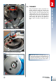
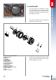
CLUTCH UNIT
You must remove the transmission control
lever and start-up lever to access the clutch
unit. Loosen the seven screws shown in the
picture that couple the internal cover of the
clutch A to the casing.
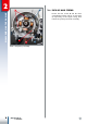
The clutch unit consists of the components
shown in the picture below.
To remove this, unthread the clutch control
rod 21 and bend it to the right of the engine
for the ball 20 to come out.
2.4
The seven screws that couple the internal cover of
the clutch to the casing.
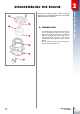
CLUTCH UNIT: MAIN COMPONENTS.
3) Washer 20x35x1;
5) Bushing;
9) Clutch bell;
10) Special washer;
11) Clutch drum;
12) Steel disc (No. 5);
13) Friction disc (No. 6);
14) Pressure plate cap;
15) Spring (No. 6);
16) Washer 6x18 (No. 6);
17) Screw 6x16 (No. 6);
18) Thrust bearing cage 15x18x2;
19) Pressure plate;
20) Ball;
21) Clutch control rod.
A