
Specifications


2
22
DISASSEMBLING THE ENGINE
INTERNAL TRANSMISSION
CONTROL AND TRANSMISSION
GEARS
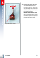
The internal transmission control is enclo-
sed inside the two engine casings. To access
this, you must remove the eleven screws that
couple the two engine casings, then decou-
ple these with the use of the special tool A
(code 01.00042.000).
Tool A must be mounted onto the right ca-
sing so as to cover the flywheel housing and
fastened to the three threaded holes of the
flywheel cover.
Then tighten the upper screw on the tool,
whilst holding the motor shaft still (e.g. by
holding the connecting rod), until the casings
are completely decoupled from each other.
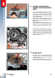
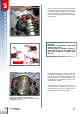
Unthread the two fork pins 1 as much as
is needed to decouple them from their re-
spective housing. Turn the pin-fork assembly
outwards, remove the desmodromic device
2, then the shaft-fork assembly. Remove the
complete gear unit whilst paying attention
to the shim washers.
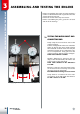
MOTOR SHAFT
Mount tool A (code 01.00042.000) onto the
left casing so as to cover the primary gear
housing, fastening it to the three threaded
holes of the right casing.
Then tighten the upper screw on the tool, un-
til the motor shaft is completely unthreaded.
2.7.2
2.8
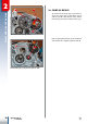
Decoupling the casings.
Forks, desmodromic control and gears.
Disassembling the motor shaft.
1
1
A
2
A