
Specifications


3
28
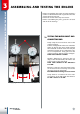
ASSEMBLING AND TESTING THE ENGINE
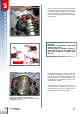
Insert the gear, then mount the fork-fork pin
assembly, whilst ensuring to first insert the
fork into the path of the specific gears. Then
turn the fork-pin assembly outwards for the
bolts to remain in the casing and not enter
their housing.
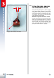
CAUTION!
Each fork is marked with a symbol that
must face the casing.
The forks must be applied according to
the mark indicated in the images. The
upper part of fork “A” is higher than
fork “B”.
Insert the desmodromic control 1 and turn
the fork-pin assembly inwards for the fork
pins to enter their respective housing in the
casing. For this to occur, the guide pins 2 on
the forks must engage with the slots on the
desmodromic control.
To verify that all operations pertaining to
the reassembly of the gear to the casing
function properly you must simply ensure
that the toothed wheels turn freely.
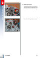
Turning the fork-pin assembly outwards and inser-
ting the desmodromic control device.
Symbols marked on forks.
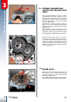
Turning the fork-pin assembly inwards and inserting
the fork pins into their respective housing.
Inserting the fork guide pins 2 into the slots of the
desmodromic device.
C
B
B
A
C
A
Attention!