
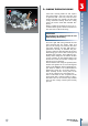
Specifications


3
31
ASSEMBLING AND TESTING THE ENGINE
3.5.2
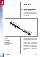
ASSEMBLING THE EXTERNAL
TRANSMISSION CONTROL
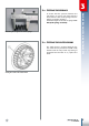
While keeping the stopping device 1 moved,
position the stop cam 2 on the protruding
end-part of the desmodromic control 3, for
opening A, which is in the lower part of the
cam, to engage with pin B, which is found
on the protruding end-part of the desmo-
dromic control.
Then mount the TSPCE fastening screw
M6x30 between the stop cam and the de-
smodromic control, after placing the me-
dium resistant thread stoppers: tighten to
11Nm.
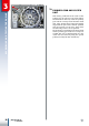
Insert the transmission control shaft into
its housing applying two specific thrust wa-
shers at the two ends of the small shaft.
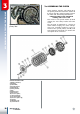
Should you wish to test the entire gearbox
unit and ensure it functions properly, tem-
porarily couple the external control lever
and simulate a gear shifting operation by
lifting and lowering the control lever. If no
abnormal blockage occurs, the entire device
is functioning correctly.
Please note that if the unit is operated wi-
thout oil, the device will be noisier than
usual.
Positioning the stop cam onto the desmodromic device.
Verifying whether the gearbox unit functions properly.
A
2
B
3
1