
Specifications


3
33
ASSEMBLING AND TESTING THE ENGINE
3.6.2
3.6.1
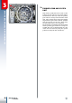
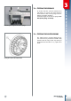
MOUNTING THE START-UP DEVICE
Insert the complete ignition shaft A into the
relative housing whilst keeping the spline
facing outwards.
Turn the shaft anti-clockwise until the stop
limit is reached and then hook the spring
return lever to the cylindrical head screw B.
If this screw (M6x20) has been disassem-
bled, tighten it with a torque of 10Nm.
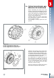
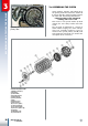
If the idler gear pin C has been disassem-
bled or replaced, tighten the relative Allen
screw (M8x20) with a torque of 23Nm.
Insert the idler gear into the relative pin and
the washer-spacer 18x27 and close the as-
sembly with the Seeger (18e). Lubricate the
assembly with transmission oil and mount
the external lever temporarily to then simu-
late ignition so as to verify that no abnormal
blockage occurs.
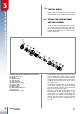
To reassemble this, insert Seeger 23, shim
washer 22, spring 21 and sleeve 20 in such
a way that the opening that will block spring
11, is aligned with the left border of the ramp
on the sleeve.
Then insert the shim washer 18, cage 17,
gear 16, shim washer 15, spring 11 and spa-
cer 14.
Positioning the sleeve onto the spindle.
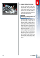
Start-up device assembly coupled with the casing.
Coupling of the complete ignition shaft to the casing.
B
A
C