
Specifications


3
38
ASSEMBLING AND TESTING THE ENGINE
3.8
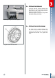
ASSEMBLING THE CLUTCH
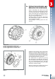
Insert washer 1 20x35x1 and bushing 2 on
the primary shaft then mount the clutch bell
3. Ensure that the radial loosening between
the clutch bell and bushing falls between:
radial loosening of the clutch bell
bushing: 0.01 to 0.11 mm
Then insert a new special washer 4, clutch
drum 5, the new safety washer 6 and the
nut 7.
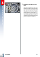
The nut must be tightened to a torque of
70Nm whilst keeping the clutch bell-pri-
mary gear assembly blocked in place by
means of the special primary tool A (code
007.14.000.0.0). Paragraph 2.4 contains the
description of its correct use.
Tightening the nut that blocks the clutch bell to the
primary shaft.
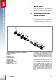
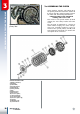
CLUTCH EXPLODED VIEW:
1) Washer 20x35x1;
2) Bushing;
3) Clutch bell;
4) Special washer;
5) Clutch drum;
6) Safety washer;
7) Nut;
8) Driving discs;
9) Driven discs;
10) Pressure plate;
11) Thrust bearing;
12) Special washer;
13) Pressure plate cap;
14) Spring;
15) Washer 6x18;
16) Screw M6x16