
Specifications


3
44
ASSEMBLING AND TESTING THE ENGINE
3.11.2
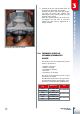
TESTING THE CYLINDER AND
HEAD
Verify that the bore falls within the limits of
service in respect to the category shown in
the table below, whilst ensuring to measure
it at the distance of X from the upper edge of
the cylinder itself.
Please note that this measurement is to be
taken by placing the bore gauge with its axis
perpendicular to the axis of the motor shaft.
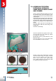
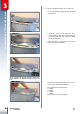
Verify the loosening between the housings
and piston rings by placing a caliper in
between.
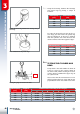
To verify the wear-and-tear state of the pi-
ston rings you must insert the piston ring
into the cylinder for its axis to be collinear
with the cylinder’s axis. Then measure the
distance between the two opposite edges.
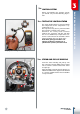
Testing the loosening between the housings and pi-
ston rings.
First verification of the piston rings.
Placing the gauge to measure the bore.
3.11.1
Cubic Capacity
[cm³]
Height X
[mm]
Limit of service according to the category
A B C D
125 10.0 54.005 54.015 54.025
200 13.0 64.005 64.015 64.025 64.035
250 10 72.515 72.525 72.535
290 10 78.015 78.025 78.035
Cubic Capacity
[cm³]
Limit of service
[mm]
125 0.18
200 0.18
250 0.14
290 0.14
X
Cubic Capacity [cm³] Limit of service [mm]
125 0.60
200 0.60
250 0.60
290 0.60