
Specifications


3
49
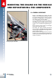
ASSEMBLING AND TESTING THE ENGINE
3.13
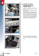
ASSEMBLING THE HEAD
Turn the flywheel to ensure that the cran-
kshaft functions correctly.
Put grease inside the threaded holes whe-
re the head locking screws will be placed.
Remove the excessive grease on the surface
where the head gasket will be placed.
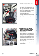
Place the gasket on the cylinder taking care
that the reference label A on the gasket must
be placed aligned with exhaust flange.
The reference label on the gasket
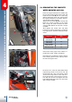
Place the O-ring in its seat on the upper ex-
ternal area of combustion chamber and pla-
ce the combustion chamber into the head
cover.
Place the head on the gasket taking care that
the arrow printed on the head cover must be
pointed towards the exhaust flange.
Place screws ( M7x31 ) in place together
with copper washers ( 7x12x0,5 ) and screw
by hand till they keep head cover in place.
Lock the screws by following 2 times the
sequence listed below. Use the following li-
sted torque according to locking sequence:
• First lock 15Nm
• Second lock 22Nm
Seal head with highlighted reference to the mount.
A
1
6
2
3
4
7
5