
User`s manual

10
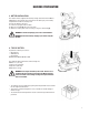
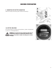
11. INSTRUMENT PANEL COMPONENTS
Theinstrumentpanelcomponentsareidentiedasfollows:
A. Levers to activate brushes / traction (located beneath the grip)
B. ON/OFF key switch
C. Battery level / hour meter
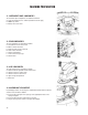
12. REAR COMPONENTS
Therearcomponentsareidentiedasfollows:
A. Foot pedal to raise the brush deck
B. Water / solution level hose
C. Drain hose with recovery tank cap
D. Latch to close the tanks
E. Storage compartment
F. Lever to raise the squeegee
G. Solution filter
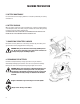
13. SIDE COMPONENTS
Thesidecomponentsareidentiedasfollows:
A. Valve for manual regulation of clean water outlet
B. Handle to raise the recovery tank
C. Handle to raise the vacuum unit
D. Upper storage compartment
E. Brake lever
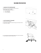
14. ASSEMBLING THE SQUEEGEE
For packaging reasons, the squeegee is supplied dismounted from the machine,
andmustbeassembledasfollows:
A. Insert the two small pins of the squeegee in the appropriate holes on the
squeegeesupport;
B. Insertthetwocotterpinschainedtothesqueegee;
C. Plug the squeegee hose into the squeegee shoe adaptor.
MACHINE PREPARATION