
Product Manual


3Rev. - 922123-01
If you require a greater initial prime height, coat the
gears with uid by removing the plug on the top of the
pump and pour a small quantity of motor oil into the gear
cavity. Replace the plug and try again. A foot valve with
pressure relief may be needed to maintain prime.
Make sure all threaded fuel connections are wrapped
with three to four turns of thread tape or a pipe thread
sealant approved for use with petroleum fuels.
Install Bung Adapter and Suction Pipe
• Tighten the bung adapter snugly into the fuel tank.
• Place the union ring gasket into the inlet tting on the
bottom of the pump.
• Thread the suction pipe into the inlet tting and tighten
until snug.
Install Pump on Tank
• Clean the tank interior of all dirt and foreign material.
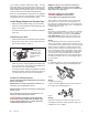
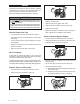
• Extend the suction pipe to its full length and insert
into the tank opening. (Figure 1)
FIGURE 1
The suction pipe
will adjust to the
length needed to
rest on the tank
bottom.
• Place the pump on the bung adapter and tighten the
union ring securely with a pipe wrench. Make sure
the union ring is not cross-threaded.
• To prevent pressure buildup and possible fuel leaks
through the nozzle, make sure the tank is vented. A
vent cap rated at 3 psi or less is recommended.
Connect to a Power Source
Please consult the Owner’s Manual for your vehicle
before proceeding.
NOTE: Models M-150S and M-180S should be con-
nected to a 12-volt DC power source.
Model M-240S should be connected to a 24-volt DC
power source.
Do not attempt connection of any pump to a 115-
volt AC or 230-volt AC power source.
WARNING: Do not attempt to power the pump
from vehicle wiring smaller than 12 gauge, such
as the cigarette lighter wire, as these thin wires
could overheat and cause a re.
NOTE: This pump is pre-wired for installation in
CLASS I, DIVISION 2 locations such as portable
fuel tanks, trailers, etc. Connection to a battery will
depend upon the application.
WARNING: If pump is to be installed in
a CLASS I, DIVISION I location please
contact GPI for the appropriate product.
Verify switch is in OFF position, then route the elec-
trical wires to the source of the vehicle power sys-
tem. Be sure to support the wires as necessary and
protect them from sharp edges, heat or anything that
could damage the wires.
Step 1
If the power cord provided is too long, cut to desired
length. Carefully strip 3 to 4 inches (7.5 to 10 cm) of
outer insulation from end of power cord. DO NOT
CUT INNER WIRES. Next, strip ¼ inch (0.6 cm) of
insulation from the black and red power cord wires.
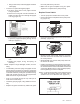
Step 2
For a negative ground system, rst disconnect the
vehicle’s ground wire, and then wire as follows: Insert
one end of the fuse (J) into the wire connector (H) and
crimp. Insert the red power cord wire into the other
end of the wire connector and crimp. Make sure the
fuse is positioned outside of hazardous areas and as
close to the battery as possible. Make a solid electri-
cal connection to the grounded side of the battery
with the remaining black wire. Connecting directly to
the battery terminal or the end of the battery cable is
recommended.
Step 3
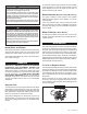
For temporary wiring: Connect the red and black pow-
er cords to alligator clamps (not included) (Figure 6).
Figure 6
Step 4
For permanent wiring:
Connect the red and black power cords to terminal
post rings (not included) (Figure 7).
Figure 7
Step 5
Check all connections to make sure they are con-
nected per instructions and all electrical codes. The
installation is now complete.