
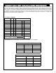
Specifications

7
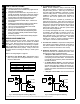
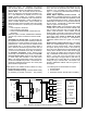
* The diodes shown above are used to reduce the electrical noise produced when internals coils of the magnetic lock are de-energized.
Fig. 6: Normally De-Energized Lock Wiring
Electric Strike
GEM-2D
5
6
32
33
COM N/O
Clamping
Diode
(supplied)*
(+) D2 PWR
(–) D2 PWR
Fig. 5: Normally Energized Lock Wiring ("Mag Lock")
Magnetic Lock GEM-2D
5
6
32
34
COM N/C
(+) D2 PWR
Clamping
Diode
(supplied)*
(–) D2 PWR
Lock Wiring for the GEM-2D
GEM-2D WIRING/CONFIGURATION
Connect 2nd Door Strike (Mag Lock).
NOTE: Before installation, always check with local
laws having jurisdiction concerning the installation of
magnetic locking devices. There may be strict limita-
tions with regard the installation of magnetic or similar
exit door locking devices. Local laws may require the
installation of electrically separate panic hardware to
ensure the door can be opened in the event of an
emergency.
Door strike outputs are controlled by schedules pro-
grammed into the panel. These door strike outputs can
operate DC-powered locking devices such as magnetic
door locks or other electromechanical locks and can be
configured to operate in "Fail Secure" (which remain
locked when power fails) or "Fail Safe" (which unlock
when power fails) configurations.
For normally closed door strikes, connect ground to ter-
minal 6, wire terminal 5 to terminal 32, then connect the
positive door strike wire to terminal 34. See Figs. 5 and
6 below. The GEM-ACM1D can supply a constant
combined maximum 12V output of 1.5A for D1-PWR
and D2-PWR.
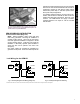
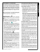
Fig. 4: Installing the GEM-2D. Before inserting, align all pins and
receptacle sockets, then fully insert the GEM-2D into receptacles J4F
and J5F located on top of the GEM-ACM1D.
SECOND DOOR INSTALLATIONS