Note: The following is a Product Review from QST that is normally available only on the ARRL MembersOnly page (along with all Product Reviews from 1980 to the present!) ARRL membership offers valuable benefits to new and experienced amateurs alike.
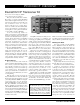
PRODUCT REVIEW Elecraft K2 HF Transceiver Kit Reviewed by Larry Wolfgang, WR1B Senior Assistant Technical Editor Okay, let’s start out with a show of hands. How many of you have built a Heathkit? That’s what I thought. Practically everyone who has been a ham for more than 20 years has assembled at least one of those classics—and the rest of you have had to listen to us reminisce about it.
Table 1 Elecraft K2, serial number 00495 Manufacturer’s Claimed Specifications Measured in the ARRL Lab Frequency coverage: Receive and transmit, 3.5-4; 7-7.3; Receive, 2.9-4.1, 6.5-7.3, 10-10.5, 13.2-14.7, 17.1-22; 10-10.2; 14-14.5; 18-18.2; 21-21.6; 24.8-25; 28-28.8 MHz. 1, 2 23.2-30.4 MHz; transmit, as specified. Modes of operation: USB, LSB, CW. As specified. Power requirement: 8.5-15 V dc, receive, 0.25 A Receive, 0.3 A (maximum volume, no signal);3 (no signal); transmit, 2.0 A, at 13.8 V. transmit, 2.
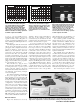
0 –60 Reference Level: 0 dB PEP –10 –70 –20 –80 –30 –90 –40 –100 –50 –110 –60 –120 –70 –130 –80 –10 –8 –6 –4 –2 0 2 4 Frequency Offset (kHz) 6 8 10 –140 2 Reference Level: - 60 dBc/Hz Vertical Scale: dBc/Hz 4 6 8 10 12 14 16 18 20 Frequency Sweep: 2 to 22 kHz from Carrier 22 Figure 1—Worst-case spectral display of the Elecraft K2 transmitter during twotone intermodulation distortion (IMD) testing.
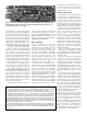
two inductors. Don’t let this happen to you! Be careful to identify the correct location for every part before you install it, and recheck before soldering. Alignment and Testing Figure 5—A closer look at the completed control board. The glass epoxy boards have plated through holes and the component identifications and locations are clearly silk-screened on the boards. quite informative. Someone mentioned that they really missed not having a dimple on the main tuning knob.
switched in.) This filter is optimized for narrow bandwidths of about 200 to 500 Hz, but it can be adjusted wider or narrower if desired. A second two-pole crystal filter follows the IF amplifier. This filter can also be tuned, but over a smaller bandwidth range. The AGC signal is derived from the IF amp output using an auxiliary low frequency IF of about 150 kHz. The Finished Product Figure 6—An internal view with the top cover removed.
Like most transceivers these days, the K2 uses a series of menu options to control other less-used functions. For example, by tapping the MENU button and then turning the tuning knob until “ST L” is shown, you can adjust the sidetone level. Dial up “ST P” and you can adjust the sidetone/ receive offset pitch. The “INP” setting allows you to select either a straight key or the normal or reversed input from paddles, and “IAB” selects either Iambic A or Iambic B type keying.
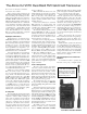
The Alinco DJ-V5TH Dual-Band FM Hand-Held Transceiver Reviewed by Joe Bottiglieri, AA1GW Assistant Technical Editor Alinco’s latest product offering for the dual-band hand-held market, the DJ-V5T, has been taking a bit of ribbing for mimicking the physical design cues of Yaesu’s FT-50RD, ICOM’s IC-T8A or Kenwood’s TH-G71A. These H-Ts are relatively short, husky little handfuls that use “clamshell” type construction—the battery packs attach to the back side of the chassis.
Table 2 Alinco DJ-V5TH, serial number T000670 Manufacturer’s Specifications Frequency Coverage: Receive, 76-108 MHz (WFM), 144-148 MHz, 420-450 MHz; transmit, 144-148 MHz, 420-450 MHz. Power requirements: 4.0-15.0 V dc; receive, 0.22 A; transmit, 1.6 A (maximum, high power). Measured in ARRL Lab Receive and transmit, as specified. Receiver Sensitivity: 12 dB SINAD, VHF, 0.16 µV; UHF, 0.18 µV; WFM, 1.0 µV. Two-tone, third-order IMD dynamic range: Not specified.