
Owner`s manual


6
OUTPUT INPUT
2+
1+
2–1–
TO
AMPLIFIER
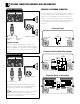
Connector Panel
OUTPUT INPUT
2+
1+
2–1–
TO
AMPLIFIER
FULL
RANGE
BI-AMP
LF
HF
Connector Panel on Multi-Way Systems
OUTPUT INPUT
PASSIVE BI-AMPLING
INPUT PASSIVE OUTPUT
2+ 2+
2– 2–
1+ 1+
1– 1–
SUB
WOOFER
INPUT BI-AMPLING OUTPUT
2+ 2+
2– 2–
1+ 1+
1– 1–
SUB
WOOFER
Connector Panel on Subwoofers
EXAMPLE OF SPEAKON CONNECTOR
There are two groups on the speakon connectors: Group 1
(+1,
–1) and Group 2 (+2, –2) as indicated in the diagram. In
order to use it, your speaker must have multi-functions (i.e.
enable two sources of signal for input). If your speaker does
not have multi-functions, it would not work with the Group 2
for connection. Please refer to the following diagram for
connection.
Speakon Outputs
The upper Speakon jack has both Channel 1 and
Channel 2 outputs, so it is especially useful for parallel,
bi-amp, or BRIDGE mono operation. The other Speakon
carries only Channel 2's output. See the illustrations at
above.
SPEAKON Y CONNECTORS
INPUT OUTPUT
L
O
C
K
L
O
C
K
TO CHANNEL 2
SPEAKER
TO CHANNEL 1
SPEAKER
2–
1–
1+ 2+
REFERENCE CONNECT
8
4
2
+
–
8
4
2
–
+
SPEAKON CONNECTORS
INPUT OUTPUT
L
O
C
K
L
O
C
K
SOURCE
(from active/powered)
BRIDGE
2–
1–
1+ 2+
REFERENCE CONNECT
8
4
2
+
–
Source (INPUT) comes from the output source of the
active/powered speaker while the bridge (OUTPUT)
connects to the passive/non-powered speaker.
A speakon cable is required to connect the “OUTPUT”
of the acive/powered speaker to the “INPUT” of the
passive/non--powered speaker. Please order the speakon
cable from our authorized dealers.
NOTE
SPEAKER CONNECTION METHODS AND INFORMATION
Conn ection
NL4 SPEAKON NL4 SPEAKON
NL4 SPEAKON
NL4
SPEAKON