KARAOKE ® Professional UHF Wireless Microphone System VM-92U Operating Instructions UHF 64 Frequency Selectable IC FM UH 32 13. 10 Z MH 2U ELE CT AB L LS NE VM -9 Bu ild er ® AN 248 CH CH sic EM ST SY rM u tte Be WIR ELE SS E F UH Better Music Builder ® UHF DUAL CHANNEL RECEIVER VM-92U AF RF CH01:752.20 mhz POWER RECEIVER - A LCD 64 SELECTABLE WIRELESS SYSTEM UP DOWN AF RF CH01:763.20 mhz MIN MAX VOLUME RECEIVER - B LCD Thank you for purchasing this unit.
CONTENTS INTRODUCTION...............................................................................2 RECEIVER SPECIFICATION.................................................................. 3 THE SYSTEM INCLUDES THE FOLLOWING PARTS................................. 4 SETTING UP YOUR RECEIVER.............................................................. 4 RECEIVER LCD PANEL DESCRIPTION.................................................... 5 HOW TO SELECT FREQUENCIES?............................................
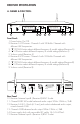
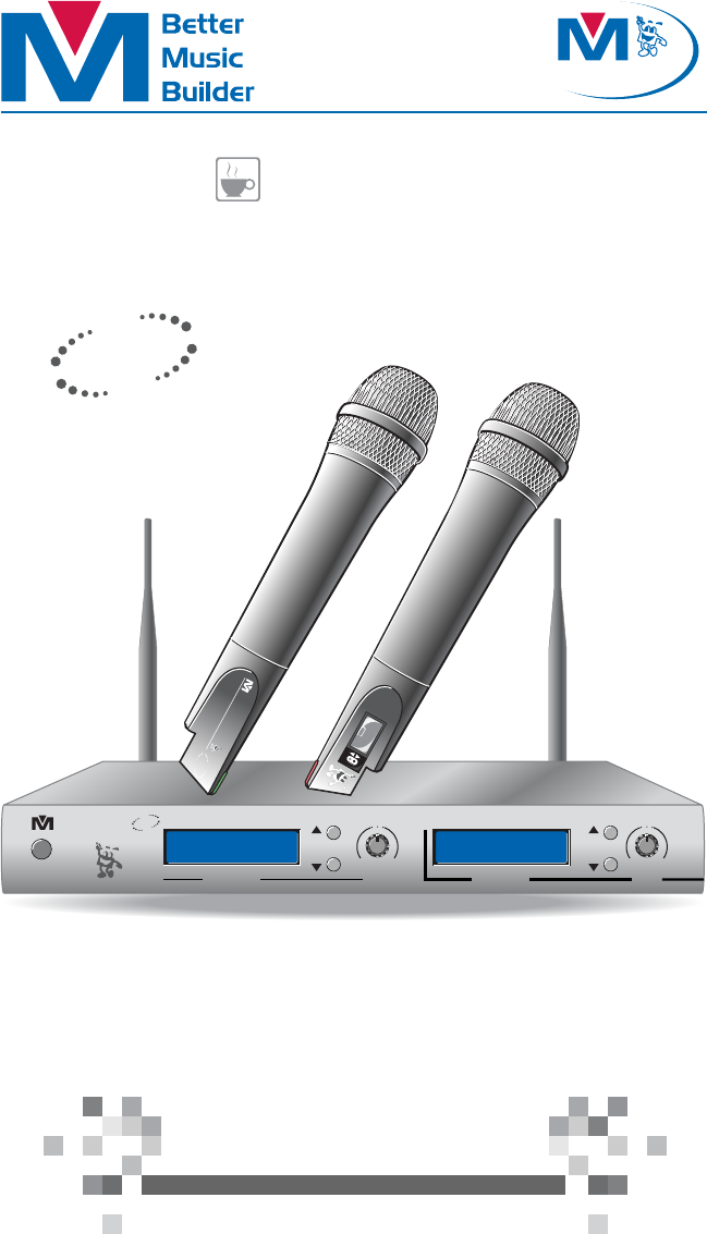
RECEIVER SPECIFICATION A. NAMES & FUNCTION: Better Music Builder ® UHF DUAL CHANNEL RECEIVER VM-92U AF RF CH01:752.20 mhz 64 SELECTABLE WIRELESS SYSTEM UP DOWN POWER AF RF CH01:763.20 mhz MIN RECEIVER - A LCD 1 2 MAX VOLUME 3 4 UP DOWN MIN RECEIVER - B LCD 5 MAX VOLUME 6 7 8 9 Front Panel: 1. Power button On/Off. 2. Receiver A LCD screen: Channel A with 32 Built-In Channels with different UHF frequencies. 3.
THE SYSTEM INCLUDES THE FOLLOWING PARTS The package comes with one receiver, two transmitters, one DC power adaptor, one audio cable, two 9V batteries, and two antennas. Better Music Builder ® UHF DUAL CHANNEL RECEIVER VM-92U AF RF CH01:752.20 mhz 64 SELECTABLE WIRELESS SYSTEM UP AF RF CH01:763.
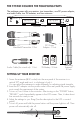
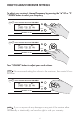
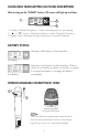
RECEIVER LCD PANEL DESCRIPTION After turning on the “POWER” button, LCD screen will light up as below: 1 3 AF RF CH01:752.20 mhz 2 1. RF (radio frequency) Indicator 2. AF (audio frequency) Indicator 3. Current Channel/Frequency Display: current value depends on your setting. NOTE If there is static or no sound coming out of your speakers, than there may be a frequency interruption from another system, change your frequency to match your transmitter’s (microphone) frequency.
HOW TO ADJUST RECEIVER SETTINGS To adjust your receiver’s channel/frequency by pressing the “▲” UP or “▼ ” DOWN button to select your frequency. UHF DUAL CHANNEL RECEIVER VM-92U UP AF RF CH08:758.30 mhz DOWN RECEIVER - A LCD UHF MIN MAX VOLUME DUAL CHANNEL RECEIVER VM-92U UP AF RF CH08:758.30 mhz DOWN RECEIVER - A LCD MIN MAX VOLUME Turn “VOLUME” button to adjust your vocal volume. NOTE We recommend setting the volume to the maximum, then control it from the mixer.
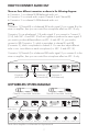
HOW TO CONNECT AUDIO OUT There are three different connectors as shown in the following diagram: • Connector 1 is a channel B XLR-balanced audio out • Connector 2 is a mixed audio output (Channel A and Channel B) • Connector 3 is a channel A XLR-balanced audio out NOTE Connector 1 (Channel B) is a balanced XLR audio signal. If you connect B to the mixer or amplifier, then you can control the microphone effect on MIC. B only. Connector 2 is an unbalanced 1/4 audio signal.
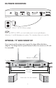
DC-POWER CONNECTION MIXED OUTPUT DC-POWER Better Music Builder ® Receiver A & B Model No. VM-92U (UHF Microphone) CALIFORNIA, UNITED STATES OF AMERICA COMMENTS? E-MAIL: info@bettermusicbuilder.com www.BetterMusicBuilder.com ENGINEERED AND DESIGN IN U.S.A. FCC: 74.861 ANTENNA-B UNBALANCED Channel B DC 14~16V 600mA RISK OF ELECTRIC SHOCK DO NOT OPEN Taking apart or modifying the receiver may lead to electric shock, fire, or damage to the receiver and will void your warranty. ANTENNA-A SERIAL NO.
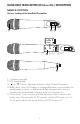
HAND-HELD TRANSMITTER (Wireless Mic.) DESCRIPTION NAMES & FUNCTION: Uncover Looking of the Handheld Transmitter: 32 CHANNEL SELECTABLE 1 2 3 9V ALKALINE BATTERY 32 CHANNEL SELECTABLE POWER 4 5 1. 2. 3. 4. Condenser and grille. LCD digital display. “▲” or “▼” buttons: Adjustment buttons to select Channel/Frequency.
HAND-HELD TRANSMITTER LCD PANEL DESCRIPTION After turning on the “POWER” button, LCD screen will light up as below: 01 806.20 1 CH 2 MHZ 3 1. Display Channel/Frequency: Current value depends on your setting. 2. “▲” or “▼” buttons: Adjustment buttons to select Channel/Frequency. 3. Battery Status: Indicates charge remaining in transmitter batteries. BATTERY STATUS Indicates a full battery on the transmitter. 01 806.20 CH MHZ Full Battery Indicates a low battery on the transmitter.
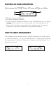
HOW TO INSERT HAND-HELD TRANSMITTER’S BATTERIES 1. Twist open battery cover. Use one hand to hold onto the top of your transmitter, use the other hand to twist out your transmitter’s handle. 32 CHANNEL SELECTABLE 2. Use one hand to hold onto the top of your transmitter, with your other hand slide one 9V battery into battery slot. Be careful not to drop transmitter while inserting battery. Make sure that you insert the battery at the right electric poles, as shown in picture.
HOW TO TURN ON AND OFF HAND-HELD TRANSMITTER Press and hold power button to turn on/off your transmitter. When on transmitter’s LCD screen will have display, when off transmitter’s LCD screen will be off. POWER Press Power button to select display options as follows: • Display Channel/Frequency NOTE After pressing the button for three seconds, the transmitter should turn on. If the transmitter is still off, please check the battery. It may very low.
TECHNICAL SPECIFICATION A. SYSTEM FEATURE: 1. 2. 3. 4. 5. 6. 7. 8. 9. 10. 11. Channel: 64 Frequency Range: 780MHz~850MHz (Selectable) Frequency Stabilization: < ±30ppm Dynamic Range: More than 90dB Total Harmonic Distortion: Less than 0.5% Audio Frequency Response: 40Hz~15KHz ±3dB Audio Output Level: Balance Output: 0~±400mV Unbalance Output: 0~±200mV Receiver Dimensions (WxHxD): 13.8x1.8x7.2 (inches)/35x4.5x18.3 (cm) Handheld Transmitter Dimensions (WxH): 1.97x10 (inches)/5x25.5 (cm) Net Weight: 6.
VM-92U FCC FREQUENCY 750 MHz and 800 MHz Group A Group B Channel Number Receiver A Frequency Receiver B Frequency Channel Number Receiver A Frequency Receiver B Frequency 1 752.200 MHz 775.200 MHz 1 763.200 MHz 787.200 MHz 2 752.500 MHz 775.500 MHz 2 763.500 MHz 787.500 MHz 3 752.800 MHz 775.800 MHz 3 763.800 MHz 787.800 MHz 4 753.100 MHz 776.100 MHz 4 764.100 MHz 788.100 MHz 5 753.400 MHz 776.400 MHz 5 764.400 MHz 788.400 MHz 6 753.700 MHz 776.700 MHz 6 764.
FREQUENCY SCAN GROUPS FOR BAND C & BAND D Band C Band C Scan Group 1 Band C Scan Group 2 Band C Scan Group 3 TV Ch. Frequency – MHz * 25 (None) 0 26 542.750 26 545.500 26 547.125 26 547.375 4 27 549.750 27 550.375 27 550.625 3 28 557.250 28 557.500 28 559.250 28 559.500 4 29 562.000 29 563.375 29 563.625 3 30 566.000 30 566.250 2 TV Ch. Frequency – MHz * 25 541.500 1 26 542.750 26 544.375 26 544.750 26 545.750 26 547.500 5 27 (None) 0 28 554.250 28 556.125 28 557.500 28 559.375 4 29 560.000 29 561.
US UHF WIRELESS OPERATING FREQUENCIES Band C: 541.500 - 566.375 MHz TV Ch. 25 --- --- --- --- 541.500 541.625 541.750 541.875 26 542.000 542.125 542.250 542.375 542.500 542.625 542.750 542.875 26 543.000 543.125 543.250 543.375 543.500 543.625 543.750 543.875 26 544.000 544.125 544.250 544.375 544.500 544.625 544.750 544.875 26 545.000 545.125 545.250 545.375 545.500 545.625 545.750 545.875 26 546.000 546.125 546.250 546.375 546.500 546.625 546.750 546.875 26 547.000 547.125 547.250 547.
Band D: 655.500 - 680.375 MHz TV Ch. 44 --- --- --- --- 655.500 655.625 655.750 655.875 45 656.000 656.125 656.250 656.375 656.500 656.625 656.750 656.875 45 657.000 657.125 657.250 657.375 657.500 657.625 657.750 657.875 45 658.000 658.125 658.250 658.375 658.500 658.625 658.750 658.875 45 659.000 659.125 659.250 659.375 659.500 659.625 659.750 659.875 45 660.000 660.125 660.250 660.375 660.500 660.625 660.750 660.875 45 661.000 661.125 661.250 661.375 661.500 661.625 661.750 661.
TROUBLESHOOTING 1. SYMPTOM: RECEIVER HAS NO POWER. If you press the power button on the receiver for more than 5 seconds, you may use the wrong DC adaptor. There are two types of adaptor; AC adaptor and DC adaptor. 2. SYMPTOM: NO SOUND Before there was sound coming from the speaker, but now there is no sound. Please check your cable connection or your battery. When you change a new battery, but there is still no sound, the battery may be placed in a wrong position inside the transmitter.
WARRANTY One-Year Limited Warranty for Home Use Equipment Our one-year warranty applies to speakers, amplifiers, mixers and microphones for home use only. It covers both parts and labors. The warranty becomes effective from the date of your purchase for one year. Our warranty only covers defects due to product defectiveness with free of defects in materials or workmanship.
Better Music Builder is a leader in the Audio and Karaoke equipment industry. We are committed to offering you the high quality audio product. We may update our manual, so we highly recommend you to download the free update from our website www.BetterMusicBuilder.com. ® Passionate about Music www.BetterMusicBuilder.com Printed on 100% Recycled Paper Comments E-mail to info@bettermusicbuilder.com Copyright © 2008 BMB :: Better Music Builder. All rights reserved. Legal trademark.