
Operating instructions
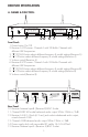
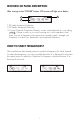
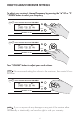
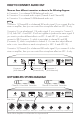
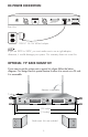
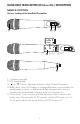
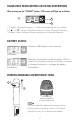
Table Of Contents

RISK OF ELECTRIC SHOCK
DO NOT OPEN
Taking apart or modifying the
receiver may lead to electric shock,
fire, or damage to the receiver and
will void your warranty.
DC-POWER
DC 14~16V 600mA
UNBALANCED
Receiver A & B
MIXED OUTPUT
0
3 61 2 0 07 1 02 3 - 92
3
ANTENNA-B ANTENNA-A
Model No. VM-92U (UHF Microphone)
CALIFORNIA, UNITED STATES OF AMERICA
COMMENTS? E-MAIL: info@bettermusicbuilder.com
www.BetterMusicBuilder.com
ENGINEERED AND DESIGN IN U.S.A.
FCC: 74.861
SERIAL NO.
Better Music Builder
®
Channel B Channel A
UHF
PO WER
Better Music Builder
®
64 SELEC TABLE WIRELESS SYSTEM
UP
DOW N
AF RF
CH01:763.20 mhz
DUAL CHA NNEL RECEIVER VM-92U
UP
DOW N
AF RF
CH01:752.20 mhz
RE CEIVER - A LC D VO LUME
MIN MA X
RE CEIVER - B LC D VO LUME
MIN MA XMIN MA X
21 43
13121110 14 15
5 6 87 9
3
RECEIVER SPECIFICATION
A. NAMES & FUNCTION:
Front Panel:
1. Power button On/Off.
2. Receiver A LCD screen: Channel A with 32 Built-In Channels with
different UHF frequencies.
3. “
▼
” DOWN button selects different frequency & model settings (Receiver A)
4. “
▲
” UP button selects different frequency & model settings (Receiver A)
5. Volume control (Receiver A)
6. Receiver B LCD screen: Channel A with 32 Built-In Channels with
different UHF frequencies.
7. “
▼
” DOWN button selects different frequency & model settings (Receiver B)
8. “
▲
” UP button selects different frequency & model settings (Receiver B)
9. Volume control (Receiver B)
Rear Panel:
10. Receiver Antenna Input-B. (Receiver B) BNC Socket.
11. Channel B XLR 3M socket balanced audio output 50Hz~15kHz +/-3dB.
12. Receiver A & B 1/4-inch (6.3 mm) jack socket unbalanced audio output,
mixed channel A & B.
13. Channel A XLR balanced audio output 50Hz~15kHz +/-3dB.
14. Power supply dock with removable IEC cable 14~16V 600mA.
15. Receiver Antenna Input-A. (Receiver A) BNC Socket.