
Manual


14
VII. EQ Filter Sections in Depth
We’ve put a large amount of time, effort, money, and listening tests into the research and development of the
analog stages of the Bettermaker EQ542. We feel that it represents one of the best values, highest delity, and
newest methods of working available in audio today. We set out to make a product that broke new ground, an
equalizer with the highest sonic quality, ease of use, and a full pallet of sound shaping tools to allow engineers to
make the best-sounding record. In the following pages, we’ll share this knowledge, show how the lters work and
interact to provide a complete sound-sculpting system.
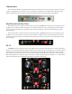
The following measurements illustrate a precision of lter implementation rarely seen in any analog equalizer.
These were taken at 96 K sample rate so they do not extend to the full 100 kHz bandwidth of the EQ542. As the
curves approach the Nyquist frequency of 48 kHz they will appear slightly deformed (though in real life they
extend symmetrically and smoothly to 100 kHz). Also, since human hearing is generally limited to under 20 kHz,
you should pay attention to how the curves look within the audible spectrum. For viewing clarity, we began our
measurement sweep at around 20 Hz and stopped it at 20 kHz or as high as 40 kHz.
HP and LP
The HP and LP are electrically connected before the EQ1/2 section and can be completely hardware bypassed
by unpressing changing their setting to bypass. HP is a forth order RC high pass lter with a 24 dB per octave
slope and a -3 dB point at the selected frequency. The corner frequency can be selected from 30 Hz to 240 Hz in
four steps. LP is a second order RC low pass lter with a 12 dB per octave slope and a -3 dB point at the selected
frequency. The corner frequency can be selected from 3 KHz to 12 KHz in four steps. As these are the rst lters
following input, it is very useful to clear out sub-sonic gunk and low frequency trash and high frequency hiss and
noise content prior to the EQ1/2 sections. If the unit appears to be clipping but with only moderate signal level,
use the HPF to improve headroom.
EQ 1/2
The EQ1/2 lter section contains two bands of fully parametric EQ, featuring a large +/-15 dB gain range
in 0.1 dB steps, and the ability to cover 3 octaves at its widest setting. It is placed after the HPF, and before the
P-Filter section. So cutting or boosting with the EQ1/2 lters will change the signal response going into the P-
Filter section. Likewise, changing the HP lter will shelve out lows from getting into the EQ1/2 lters.
EQ1/2 Topology
The EQ1/2 parametric section is based on the classic state-variable lter circuit. A ltered signal is summed
with the dry signal in phase for boost. For cuts, the dry signal is combined with the out-of-phase ltered signal
which results in perfect reciprocal curves. If you set one band to full boost, and the other band to full cut on the
same frequency, the resulting overall EQ curve will be at with almost no phase deviation. Or you could virtually
“undo” a previous-recorded mistake if you only knew the settings of a previous equalization—but you will know,
since you will have stored those settings in the EQ542 memory! This state-variable lter design allows for a large
range of bandwidth while staying extremely stable. EQ1/2’s range reaches from 3 full octaves all the way down to
1/5 of an octave, making an outstanding sound sculpting device.