
Manual


8
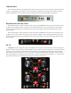
Clip Indicators
Two red LEDs illuminate if the headroom has been exceeded. This can occur by driving a signal too hard into
the EQ, or by applying too much boost in any of the bands. Clip detectors are located at the output of the lter
stage. If clipping does occur, lower the input level feeding into the unit until the LEDs stop blinking.
High Pass and Low Pass Filters
The High Pass Filter is located on the lower left of the panel. The HP knob selects the corner frequency of the
24 dB-per-octave high pass lter. The range is from 30 Hz to 240 Hz in 4 steps. All signals above the selected
frequency are passed along to the next lter section and onto the outputs. This is the rst lter that the signal
passes through.
The Low Pass Filter is located on the lower left of the panel. The
LP knob selects the corner frequency of the
12 dB-per-octave low pass lter. The range is from 3 KHz to 12 KHz in 4 steps. All signals below the selected
frequency are passed along to the next lter section and onto the outputs. This is the second lter that the signal
passes through.
EQ 1/2
The EQ 1/2 section occupies the space n the middle of the front panel. Each band of this reciprocal parametric
EQ has 3 controls (level, frequency, and bandwidth). The two knobs control level (EQ boost or cut) and frequency
respectively. The two buttons in the middle of each band alter the bandwidth of the lter. This can be changed
from 1/5th an octave at its narrowest, to 3 octaves at its widest. The EQ1 lter has a frequency range of 45 Hz to 1
kHz. The EQ2 lter has a frequency range of 650 Hz to 15 kHz. The gain range of each lter is +/- 15 dB. On the
right side of the lters you can nd the bypass (EQ x in) buttons of each lter.