BEDIENUNGSANLEITUNG OPERATING INSTRUCTIONS NOTICE D’UTILISATION MCS 20 Kabelgebundenes Konferenzsystem Wired Conference System Système de conférence à fil
1. Einführung . . . . . . . . . . . . . . . . . . . . . . . . . . . . . . . . . . . . . . . . . . . . . . . . . . . 4 2. Netzgerät MCS 20. . . . . . . . . . . . . . . . . . . . . . . . . . . . . . . . . . . . . . . . . . . . . . 4 2.1 Sicherheitsinformationen . . . . . . . . . . . . . . . . . . . . . . . . . . . . . . . . . . . . . . . . . 4 2.2 Bedienelemente. . . . . . . . . . . . . . . . . . . . . . . . . . . . . . . . . . . . . . . . . . . . . . . . 6 2.3 Bedienhinweise . . . . . . . . . . . . . . . . .
MCS 20 – Netzgerät 4 Sie haben sich für das kabelgebundene Konferenzsystem MCS 20 von beyerdynamic entschieden. Wir danken für Ihr Vertrauen. Nehmen Sie sich bitte einige Minuten Zeit und lesen Sie diese Bedienungsanleitung vor Inbetriebnahme aufmerksam durch. Folgende Komponenten gehören zur Grundausstattung eines Systems: • Netzgerät MCS 20 • Delegiertensprechstelle MCS 221 • Präsidentensprechstelle MCS 223 1.
Ventilation • Dieses Gerät benötigt eine ausreichende Ventilation. Decken Sie die Lüftungsöffnungen nicht ab. Wenn die Eigenwärme nicht abgeführt wird, kann das Gerät beschädigt oder brennbare Materialien in unmittelbarer Nähe können entzündet werden. Achten Sie daher darauf, dass die Luft durch die Lüftungsöffnungen frei zirkulieren kann und halten Sie brennbare Materialien fern. • Stecken Sie keine Gegenstände in die Lüftungs- und andere Öffnungen.
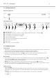
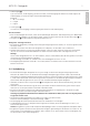
MCS 20 – Netzgerät 6 2.2 Bedienelemente MCS 20 Vorderansicht MCS 20 Rückansicht Betriebsanzeige Audioeingang, 3-pol. XLR, symmetrisch, erdfrei, regelbar über Potentiometer „Input Level“ Audioausgang, 3-pol. XLR, symmetrisch, erdfrei Line-Ausgang, z.B. für Tonaufzeichnungsgerät Regler für Eingangspegel Anschluss für weitere Netzgeräte / Systemerweiterung Anschluss für Sprechstellen Netzschalter Netzanschluss mit Sicherungshalter 2.
• Audioausgang 3-pol. XLR-Stecker, +6 dB Ausgang, symmetrisch erdfrei, Summenausgang aller Mikrofone und des Signals des Audioeingangs, für Aufzeichnungen und Rundfunkübertragung. Belegung: 1 = NC - nicht belegt 2 = +Signal 3 = -Signal • Line-Ausgang Cinch-Buchse, Line-Ausgang; Summenausgang aller Mikrofone und Audioeingang. Ein-/Ausschalten • Bevor Sie das Netzgerät einschalten, sollten Sie alle Verbindungen überprüfen.
MCS 20 – Sprechstelle MCS 221 3. 8 Sprechstellen 3.1 Sicherheitsinformationen Allgemein • Die Sprechstelle verfügt über ein Schwanenhalsmikrofon. Passen Sie auf, dass Sie sich an diesem nicht verletzen, z.B. ins Auge bohren. • Zum Ausrichten des Schwanenhalsmikrofons der Sprechstelle und zum Vermeiden einer Überdehnung sowie frühzeitigen Verschleißerscheinungen, fassen Sie das Mikrofon immer am unteren flexiblen Teilstück an, niemals oben am Mikrofonkopf oder am starren Rohr.
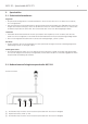
MCS 20 – Sprechstelle MCS 221 Ansicht von oben deutsch Ansicht von unten 9 Konfigurationsschalter (DIP-Schalter) Schwanenhalsmikrofon mit Leuchtring Mikrofontaste mit LED Lautsprecher 3.2.1 Bedienung Delegiertensprechstelle MCS 221 • Zum Sprechen muss das Mikrofon der Delegiertensprechstelle MCS 221 aktiviert sein. Bei einem eingeschalteten Mikrofon leuchtet der Leuchtring am Schwanenhals sowie die LED in der Mikrofontaste .
MCS 20 – Sprechstelle MCS 221 3.2.2 10 Konfigurationsschalter • Auf der Unterseite der Delegiertensprechstellen befinden sich Konfigurationsschalter, die einer Sprechstelle je nach Stellung ON bzw. OFF, die in der Tabelle aufgelisteten Funktionen zuweisen. Zum Programmieren der von den Standardfunktionen abweichenden Funktionen der Präsidentensprechstelle MCS 223 siehe Kapitel 3.3.8 „Programmiermodus“ und 3.3.9 „Programmierungsfunktionstabelle“.
2 OFF – Sprechstelle wird für das Limit im VOICE-Betrieb nicht mitgezählt Dieser Schalter gilt nur für die Delegiertensprechstelle MCS 221. 3 OFF – Limit gilt nicht für diese Sprechstelle Der Redner kann diese Sprechstelle auch dann einschalten bzw. anmelden, wenn jeweils das Limit bereits erreicht ist. 4 OFF – VOICE-Betrieb nicht erlaubt Wenn dieser Schalter auf OFF steht, ist die sprachgesteuerte Einschaltung nicht möglich (auch wenn diese Betriebsart durch den Präsidenten gewählt wurde).
MCS 20 – Sprechstelle MCS 223 12 3.3 Bedienelemente Präsidentensprechstelle MCS 223 Ansicht von hinten Ansicht von oben Konferenzbuchse; Anschluss von/zur nächsten Sprechstelle bzw. Anschluss an Netzgerät Kopfhöreranschluss, Klinke 3,5 mm Konferenzbuchse; Anschluss von/zur nächsten Sprechstelle bzw.
MCS 20 – Sprechstelle MCS 223 „Limit“-Tasten zum Einstellen der zugelassenen Anzahl eingeschalteter bzw.
MCS 20 – Sprechstelle MCS 223 14 • Für die Präsidentensprechstelle kann, abweichend von der allgemeinen Voice-Schwelle, eine eigene gewählt werden. • Die Einstellung für die Einschaltschwelle wird automatisch gespeichert und bei jedem Einschalten des Netzgerätes wieder geladen. • Der Wert der Einschaltschwelle sollte vor Ort angepasst werden, da auch der Abstand der Sprechstellen zueinander und die Raumakustik die Einschaltung der Mikrofone beeinflussen.
• Das Limit gilt jeweils für die aktivierte Betriebsart, die durch die leuchtende LED im „Mode“-Feld angezeigt wird. • Wählen Sie die Betriebsart, für welche das Limit eingestellt werden soll. Die gewählte Betriebsart wird durch die leuchtende LED angezeigt. • Setzen Sie das Limit, indem Sie die [+] oder [-]-Taste drücken, bis die gewünschte Zahl im Display erscheint.
MCS 20 – Sprechstelle MCS 223 16 • Schritt 1 – Limit auf 01 setzen Das Limit für die gewünschte Betriebsart („Free“ oder „Request“) sollte zuerst auf 01 gesetzt werden. Bei einem Limit von >1 gilt die angezeigte Redezeit der zuerst eingeschalteten Sprechstelle auch für alle weiteren Einschaltungen innerhalb des Limits. Folglich würden diese Sprechstellen mit Ablauf der zuerst eingeschalteten Sprechstelle mit abgeschaltet werden.
MCS 20 – Sprechstelle MCS 223 • Schritt 4 – Timermodus verlassen ohne Löschen eingeschalteter Mikrofone Drücken und halten Sie die „Prior“-Taste und drücken Sie kurz die „Clear“-Taste . Im Display erscheint wieder das Limit der aktivierten Betriebsart. ODER Timermodus verlassen mit Löschen eingeschalteter Mikrofone Drücken und halten Sie die „Clear“-Taste und drücken Sie kurz die „Prior“-Taste . Im Display erscheint wieder das Limit der aktivierten Betriebsart. 3.3.
MCS 20 – Sprechstelle MCS 223 18 • Schritt 4 – eingestellten Wert ändern Drücken Sie eine der „Vol“-Tasten , bis der gewünschte Wert im Display erscheint. • Schritt 5 – Zur Funktionsanzeige zurückkehren Drücken Sie die Limit [+] oder [-]-Taste, um von der Anzeige des eingestellten Wertes (blinkender Punkt rechts) zur Funktionsanzeige (blinkender Punkt links) zu wechseln. Stellen Sie weitere Werte beliebiger Funktionen ein, indem Sie wieder bei Schritt 3 beginnnen.
MCS 20 – Sprechstelle MCS 223 ODER Drücken Sie gleichzeitig die „Voice“- und die „Requ“-Taste (die „Voice“-Taste zuerst drücken), um den Programmiermodus zu verlassen. Hinweis: Über die in den Setups gespeicherten Einstellungen sollten Aufzeichnungen (z.B. in einer Kopie der Funktionstabelle) hergestellt werden. Setups laden • Das Laden von Setups verläuft analog zum Speichern, außer dass bei Schritt 4 die „Prior“-Taste anstelle der Mikrofontaste gedrückt wird.
MCS 20 – Sprechstelle MCS 223 20 3.3.9 Programmierungsfunktionstabelle Nr. Beschreibung Wertebereich Werkseinstellung 00 Setups speichern bzw. laden 1 ... 7 - 01 max. Lautstärke 0 ... 32 32 02 Lautstärkeverstellung über die „Vol“-Tasten 1 = erlaubt 0 = gesperrt 0 oder 1 1 03 max. Limit für „Voice“-Modus 0 ... 8 8 04 max. Limit für „Free“-Modus 0 ... 8 8 05 max. Limit für „Request“-Modus 0 ...
MCS 20 – Sprechstelle MCS 223 Nr. Beschreibung Wertebereich Werkseinstellung 14 „FiFo“ = „Requ“ + „Free“: 0 = MCS 223 schaltet andere Sprechstellen nicht aus 1 = MCS 223 schaltet andere Sprechstellen aus 0 oder 1 1 15 „FiFo“ = „Requ“ + „Free“: 0 = MCS 223 wird von anderen Sprechstellen nicht ausgeschaltet 1 = MCS 223 wird von anderen Sprechstellen ausgeschaltet 0 oder 1 1 16 Warnsignal im „Free“-Modus vor Ende der Redezeit; 0 = kein Warnsignal 0 ... 59 Sek.
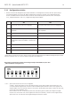
MCS 20 – Systemkonfiguration 4. 22 Beispiele Systemkonfiguration Konfiguration mit einem Netzgerät MCS 20 weitere MCS 221 MCS 20 MCS 221 MCS 221 MCS 223 Hinweis: Pro Netzgerät können maximal 60 Sprechstellen in Summe angeschlossen werden.
MCS 20 – Systemkonfiguration 23 weitere MCS 221 T-Adapter MCS 20 MCS 221 MCS 221 MCS 223 weitere MCS 221 MCS 221 MCS 221 MCS 221 Hinweis: Es kann nur eine Präsidentensprechstelle MCS 223 angeschlossen werden 5. Technische Daten Netzgerät MCS 20 Frequenzgang . . . . . . . . . . . . . . . . . . . . . . . . . . . . . 50 - 20.000 Hz Eingangsleistung . . . . . . . . . . . . . . . . . . . . . . . . . . . 250 VA Ausgangsleistung . . . . . . . . . . . . . . . . . . . . . . . . . . 150 W Ausgangsstrom .
MCS 20 – Zubehör 6. 24 Pflege • Reinigen Sie die Sprechstellen nur mit einem leicht feuchtem oder trockenem Tuch. Verwenden Sie niemals Lösungsmittel, da diese die Oberfläche beschädigen. Achten Sie darauf, dass kein Wasser in den Mikrofonkopf dringt. 7. Zubehör 7.1 Lieferzubehör MCS 20 • Netzkabel • Erweiterungskabel CA 1801, 0,3 m lang • Anschlusskabel CA 1810, 10 m lang MCS 221 • Kabel CA 1802, ca. 2,5 m lang MCS 223 • Kabel CA 1802, ca. 2,5 m lang • Bedienungsanleitung 7.
MCS 20 – Kabelspezifikation Kabelspezifikation für selbst konfektionierte Kabel deutsch 8.
1. Introduction. . . . . . . . . . . . . . . . . . . . . . . . . . . . . . . . . . . . . . . . . . . . . . . . . . 28 2. MCS 20 power supply unit . . . . . . . . . . . . . . . . . . . . . . . . . . . . . . . . . . . . . . 28 2.1 Safety information. . . . . . . . . . . . . . . . . . . . . . . . . . . . . . . . . . . . . . . . . . . . . 28 2.2 Controls and indicators . . . . . . . . . . . . . . . . . . . . . . . . . . . . . . . . . . . . . . . . . 30 2.3 Operation . . . . . . . . . . . . . . . . . . . . .
MCS 20 – Power Supply Unit 28 Thank you for selecting the wired MCS 20 conference system from beyerdynamic. Please take some time to read through this manual carefully before using this product. One system includes the following components: • MCS 20 power supply unit • MCS 221 delegate microphone unit • MCS 223 chairman microphone unit 1. Introduction The MCS 20 system from beyerdynamic is a reliable conference system which provides versatility, easy handling and quality.
MCS 20 – Power Supply Unit 29 Fire hazard • Never place naked flames near the equipment. Humidity • Never expose the equipment to rain or a high level of humidity. For this reason do not install it in the immediate vicinity of swimming pools, showers, damp basement rooms or other areas with unusually high atmospheric humidity. • Never place objects containing liquid (e.g. vases or drinking glasses) on the equipment. Liquids in the equipment could cause a short circuit.
MCS 20 – Power Supply Unit 30 2.2 Controls and indicators MCS 20 front view MCS 20 rear view Power on LED Audio input, 3-pin XLR, balanced, ungrounded, adjustable via “Input Level” potentiometer Audio output, 3-pin XLR, balanced, ungrounded Line output, e.g. for recorders Input level control Connection for more power supply units / system extension Connection for microphone units On/Off switch Power connection with fuse holder 2.
MCS 20 – Power Supply Unit 31 • Line output , RCA socket, line output; master output of all microphones and audio input. Turning on/off • Check all connections before turning on the power supply unit. A mains voltage between 100 and 240 V is suitable, because a change over to another voltage is not necessary. Turn on the MCS 20 systems with the power switch . • The green LED on the front indicates the operating status.
MCS 20 – MCS 221 Microphone Unit 3. 32 Microphone units 3.1 Safety information General • The microphone units provide a gooseneck microphone. Take care that you do not injure yourself on this e.g. poke it into your eye. • To align the gooseneck microphone on the microphone station and to avoid twisting it too far and causing premature wear, always grip the microphone by the bottom flexible section never by the microphone head or by the rigid tube.
MCS 20 – MCS 221 Microphone Unit Top view english Bottom view 33 Configuration switches (DIP switches) Gooseneck microphone with LED ring Microphone button with LED Loudspeaker 3.2.1 How to operate the MCS 221 delegate microphone unit • For speaking, the microphone of the MCS 221 delegate microphone unit has to be activated. When the microphone is activated, the LED ring of the gooseneck microphone and the LED of the microphone button will illuminate.
MCS 20 – MCS 221 Microphone Unit 3.2.2 34 Configuration switch • At the bottom of the delegate microphone units there are configuration switches. Depending on the “ON” or “OFF” position, the functions listed in the table below are allocated. For programming functions of the MCS 223 chairman microphone unit, please refer to chapter 3.3.8 “Programming mode” and 3.3.9 “Table of programmable functions”.
MCS 20 – MCS 221 Microphone Unit 35 2 OFF – Microphone unit is not counted to the limit in the “VOICE” operation This switch refers only to the MCS 221 delegate microphone unit. 4 OFF – VOICE operation not allowed When this switch is set to “OFF”, the voice-controlled activation is not possible (whether this operation mode has been selected by the chairman). It can be activated with the microphone button, when switch 8 or 5 is set to “ON”.
MCS 20 – MCS 223 Microphone Unit 36 3.3 MCS 223 chairman microphone unit - controls and indicators Rear view Top view Conference socket to connect to the next microphone unit or to the power supply unit Headphone connection, mini jack (3.
MCS 20 – MCS 223 Microphone Unit “Limit” buttons to set the allowed number of activated or registered microphone units Volume buttons to set the system volume for all microphone units Activate / deactivate timer mode (button combination “Prior” + “Clear”) Programming mode (button combination “Voice” + “Requ”) The programming mode of the chairman microphone unit and the configuration switches of the delegate microphone units allow a customised operation of the system in addition to the standard settings. 3.
MCS 20 – MCS 223 Microphone Unit 38 FiFo (first in - first out) • The “FiFo” operating mode is selected with the button combination “Free” and “Requ” . Both LEDs of the “Free” + “Requ” buttons will illuminate. • When another microphone unit is activated, the microphone unit of the current speaker is deactivated. The limit in this operating mode is 01. • In the standard setting this function also refers to the chairman microphone unit.
MCS 20 – MCS 223 Microphone Unit 39 Limit value Operating mode 00 - 08 “Voice”, “Free”, “Request” 00 - 01 “FiFo” (button combination: “Free” + “Requ” 00 - 01 “Free” with timer (button combination: “Prior” + “Clear”) “Request” with timer (button combination: “Prior” + “Clear”) • The buttons provide an auto-repeat function; i.e. the setting is automatically stored and loaded when the system is turned on again. • The maximum selectable limit value is 08. The value can be reduced by programming.
MCS 20 – MCS 223 Microphone Unit 40 • Step 1 – Set limit to 01 The limit for the selected operating mode (“Free” or “Request”) should be set to 01. With a limit of >1 the displayed speech time of the microphone unit turned on first applies to all microphone units turned on within the limit. Consequently, these microphone units will also be turned off, when the first microphone unit is turned off. • Step 2 – Settings The settings can be programmed and differ from the standard settings. Refer to chapter 3.
MCS 20 – MCS 223 Microphone Unit 41 • Step 4 – Leave timer function without clearing turned on microphones Hold down the “Prior” button and press the “Clear” button briefly. The limit of the activated operating mode is displayed . Leave the timer function with clearing turned on microphones Hold down the “Clear” button and press the “Prior” button briefly. The limit of the activated operating mode is displayed . 3.3.
MCS 20 – MCS 223 Microphone Unit 42 • Step 4 – How to change the selected value Press one of the “Vol” buttons , until the requested value is displayed . • Step 5 – How to return to the function display Press the [+] or [-] limit button to change from the displayed selected value (flashing full stop on the right) to the function display (flashing full stop on the left). Adjust further values of any functions by starting with step 3.
MCS 20 – MCS 223 Microphone Unit 43 0.6 full stop after the left number is flashing function 06 • Step 2 – How to select function 00 (setup menu) Press the [-] “Limit” button , until the function number 00 is displayed. • Step 3 – How to select the setup number Press one of the “Vol” buttons , until the requested setup number (1 - 7) is displayed . The full stop after the right number is flashing. • Step 4 – How to load the setup Press the “Prior” button to load the saved setup.
MCS 20 – MCS 223 Microphone Unit 44 3.3.9 Table of programmable functions No. Description Value range Factory setting 00 Save or load setups 1 ... 7 - 01 Max. volume 0 ... 32 32 02 Volume setting with the “Vol” buttons 1 = enabled 0 = disabled 0 or 1 1 03 Max. limit for “Voice” mode 0 ... 8 8 04 Max. limit for “Free” mode 0 ... 8 8 05 Max. limit for “Request” mode 0 ...
MCS 20 – MCS 223 Microphone Unit No. Description Value range Factory setting 14 “FiFo” = “Requ” + “Free”: 0 = MCS 223 does not turn off another microphone unit 1 = MCS 223 turns off another microphone unit 0 or 1 1 15 “FiFo” = “Requ” + “Free”: 0 = MCS 223 is not turned off by another microphone unit 1 = MCS 223 is turned off by another microphone unit 0 or 1 1 16 Warning signal in the “Free” mode before the speech time has elapsed; 0 = no warning signal 0 ... 59 sec.
MCS 20 – System Configuration 4. 46 Examples for a system configuration Configuration with a MCS 20 power supply unit further MCS 221 MCS 20 MCS 221 MCS 221 MCS 223 Note: A maximum of 60 microphone units can be connected to one power supply unit.
MCS 20 – System Configuration 47 Configuration with T-adapter T-adapter MCS 20 MCS 221 MCS 221 MCS 223 further MCS 221 MCS 221 MCS 221 MCS 221 Note: Only one MCS 223 chairman microphone unit can be connected. 5. Technical specifications MCS 20 power supply unit Frequency response. . . . . . . . . . . . . . . . . . . . . . . . . 50 - 20,000 Hz Input power . . . . . . . . . . . . . . . . . . . . . . . . . . . . . . 250 VA Output power . . . . . . . . . . . . . . . . . . . . . . . . . . . . .
MCS 20 – Accessories 6. 48 Maintenance • Only clean the microphone units with a slightly damp or dry cloth. Never use cleansing agents containing solvents as these damage the surface. Make sure not to allow any water to enter the microphone head. 7. Accessories 7.1 Supplied accessories MCS 20 • Power cable • CA 1801 extension cable, 0.3 m long • CA 1810 connecting cable, 10 m long MCS 221 • CA 1802 cable, approx. 2.5 m long MCS 223 • CA 1802 cable, approx. 2.5 m long • Operating instructions 7.
MCS 20 – Cable Specifications Cable specifications for self-made cables english 8.
1. Introduction. . . . . . . . . . . . . . . . . . . . . . . . . . . . . . . . . . . . . . . . . . . . . . . . . . 52 2. Appareil d’alimentation MCS 20 . . . . . . . . . . . . . . . . . . . . . . . . . . . . . . . . . . 52 2.1 Consignes de sécurité . . . . . . . . . . . . . . . . . . . . . . . . . . . . . . . . . . . . . . . . . . 52 2.2 Eléments de commande . . . . . . . . . . . . . . . . . . . . . . . . . . . . . . . . . . . . . . . . 54 2.3 Consignes d’utilisation. . . . . . . . . . . . . . . . . . .
MCS 20 – Appareil d’alimentation 52 Vous avez opté pour le système de conférence à fil MCS 20 de beyerdynamic. Nous vous remercions pour la confiance que vous nous accordez. Veuillez prendre le temps de lire attentivement cette notice d’utilisation avant la mise en service du produit. Votre système intègre les composants de base suivants : • Appareil d’alimentation MCS 20 • Poste délégué MCS 221 • Poste président MCS 223 1.
MCS 20 – Appareil d’alimentation 53 Connexion • L’appareil doit être raccordé à une prise correctement mise à la terre. • Posez les câbles de façon à ce qu’ils ne soient pas courbés, voire coupés pas des objets coupants. • Posez les câbles de telle sorte qu’on ne puisse trébucher dessus et se blesser. • Déconnectez toujours l’alimentation de courant avant de procéder à des travaux sur les entrées et les sorties. • Vérifiez si les puissances connectées correspondent à l’alimentation secteur existante.
MCS 20 – Appareil d’alimentation 54 2.2 Éléments de commande Vue avant MCS 20 Vue arrière MCS 20 Témoin de fonctionnement Entrée audio, XLR 3 pôles, symétrique, sans mise à la terre, réglable via potentiomètre «Input Level» Sortie audio, XLR 3 pôles, symétrique, sans mise à la terre Sortie ligne, p. ex.
MCS 20 – Appareil d’alimentation 55 • Sortie audio Prise XLR 3 pôles, sortie +6 dB, symétrique, sans mise à la terre, sortie principale de tous les microphones et du signal de l’entrée audio, pour enregistrements et transmission radio. Affectation : 1 = NC – non affecté 2 = signal+ 3 = signal- Mise en marche/hors-circuit • Avant d’allumer l’appareil, veuillez vérifier tous les branchements.
MCS 20 – Poste d’appel MCS 221 3. 56 Postes d’appel 3.1 Consignes de sécurité Généralités • Le poste d’appel est équipé d’un microphone à col de cygne. Veillez à ne pas vous blesser avec le microphone, par. ex. à ne pas vous l’enfoncer dans l’œil. • Pour orienter le microphone du poste d’appel et afin d’éviter un allongement excessif et une usure prématurée, veuillez uniquement manipuler sa partie flexible et non la tête ou le tube rigide. Le col de cygne peut être fléchi à 90° maximum.
MCS 20 – Poste d’appel MCS 221 Vue de dessus français Vue de dessous 57 Commutateur de configuration (commutateur DIP) Microphone à col de cygne avec anneau lumineux Touche de microphone avec DEL Haut-parleur 3.2.1 Commande du poste délégué MCS 221 • Pour parler, le microphone du poste délégué MCS 221 doit être activé. Lorsque le microphone est activé, l’anneau du col de cygne et la diode de la touche de microphone sont allumés.
MCS 20 – Poste d’appel MCS 221 3.2.2 58 Commutateurs de configuration • Sur le dessous des postes d’appel se trouvent des commutateurs de configuration permettant, selon réglage sur ON ou sur OFF, d’attribuer au poste les fonctions mentionnées dans le tableau. Pour programmer les fonctions du poste président MCS 223 différant des fonctions standard, veuillez vous reporter aux Chapitres 3.3.8 «Mode de programmation» et 3.3.9 «Tableau fonctionnel de programmation».
MCS 20 – Poste d’appel MCS 221 59 2 OFF – Le poste d’appel n’est pas pris en compte dans la limite en mode VOICE. Ce commutateur ne vaut que pour le poste délégué MCS 221. 3 OFF – La limite ne vaut pas pour ce poste d'appel. L’orateur peut activer ce poste, en l’occurrence demander la parole même lorsque la limite a respectivement déjà été atteinte.
MCS 20 – Poste d’appel MCS 223 60 3.
MCS 20 – Poste d’appel MCS 223 Touche Prior (priorité) pour une brève interruption, p. ex.
MCS 20 – Poste d’appel MCS 223 62 • La valeur sélectionnée pour le seuil d’activation est automatiquement mémorisée et chargée lors de chaque mise en marche de l’appareil d’alimentation. • Il est recommandé de régler le seuil d’activation sur le lieu même de la conférence. En effet, la distance entre les postes et l’acoustique de la salle exercent une influence sur l’activation des microphones.
MCS 20 – Poste d’appel MCS 223 63 Valeur limite Mode de fonctionnement 00 - 08 Voice, Free, Request 00 - 01 FiFo (combinaison de touches: «Free» + «Requ») 00 - 01 Free avec Timer (combinaison de touches: «Prior» + «Clear») Request avec Timer (combinaison de touches: «Prior» + «Clear») • Le réglage est automatiquement enregistré et conservé lors de la prochaine mise en marche du système. • La valeur maximale pouvant être sélectionnée est 08. Cette valeur peut être diminuée par programmation.
MCS 20 – Poste d’appel MCS 223 64 • Etape 1 – Réglage de la limite sur 01 Nous recommandons de régler la limite pour le mode de fonctionnement souhaité («Free» ou «Request») tout d’abord sur 01. En effet, en présence d’une limite >1, le temps de parole du poste d’appel activé en premier lieu vaut également pour tous les autres postes activés ultérieurement à l’intérieur de la limite. A la fin du temps de parole fixé pour le premier poste, les autres postes seraient par conséquent également désactivés.
MCS 20 – Poste d’appel MCS 223 65 • Etape 4 – Quitter le mode Timer sans effaçage de microphones actifs Pressez la touche «Prior» et maintenez-la enfoncée, pressez brièvement la touche «Clear» . La limite pour le mode de fonctionnement activé apparaît de nouveau à l’écran . OU Quitter le mode Timer avec effaçage de microphones actifs Pressez la touche «Clear» et maintenez-la enfoncée, pressez brièvement la touche «Prior» .
MCS 20 – Poste d’appel MCS 223 66 • Etape 4 – Modification de la valeur réglée Pressez l’une des touches «Vol» jusqu’à ce que la valeur souhaitée apparaisse sur l’écran . • Etape 5 – Retour à l’affichage de la fonction Pressez la touche Limit [+] ou [-] pour passer de l’affichage de la valeur réglée (point clignotant à droite) à l’affichage de la fonction (point clignotant à gauche). Pour régler individuellement d’autres valeurs relatives à des fonctions diverses, recommencez à partir de l’étape 3.
MCS 20 – Poste d’appel MCS 223 67 Chargement des setups • Le chargement de setups s’effectue de manière analogue à leur mémorisation si ce n’est qu’à l’étape 4, la touche «Prior» est ici pressée au lieu de la touche de microphone . • Etape 1 – Activation du mode de programmation Pressez simultanément pendant quelques secondes les touches «Voice» et «Requ» (presser tout d’abord la touche «Voice» ) jusqu’à ce qu’un numéro de fonction apparaisse sur l’écran (cf.
MCS 20 – Poste d’appel MCS 223 68 3.3.9 Tableau fonctionnel de programmation N° Description Plage de valeurs Réglage usine 00 Mémorisation ou chargement des setups 1 ... 7 - 01 Volume sonore maximal 0 ... 32 32 02 Réglage du volume sonore via touches «Vol» 1 = autorisé 0 = bloqué 0 ou 1 1 03 Limite maximale pour le mode «Voice» 0 ... 8 8 04 Limite maximale pour le mode «Free» 0 ... 8 8 05 Limite maximale pour le mode «Request» 0 ...
MCS 20 – Poste d’appel MCS 223 Description Plage de valeurs Réglage usine 14 FiFo = Requ + Free: 0 = MCS 223 ne désactive pas d’autres postes 1 = MCS 223 désactive d’autres postes 0 ou 1 1 15 FiFo = Requ + Free: 0 = MCS 223 n’est pas désactivé par d’autres postes d’appel 1 = MCS 223 est désactivé par d’autres postes d’appel 0 ou 1 1 16 En mode «Free», signal avertisseur avant la fin du temps de parole; 0 = pas de signal avertisseur 0 ...
MCS 20 – Configuration du système 4. 70 Exemple de configuration système Configuration avec un appareil d’alimentation MCS 20 autres MCS 221 MCS 20 MCS 221 MCS 221 MCS 223 Note: en tout, jusqu’à 60 postes d’appel peuvent être raccordés à un appareil d’alimentation.
MCS 20 – Configuration du système 71 Configuration avec adaptateur T autres MCS 221 MCS 20 MCS 221 MCS 221 MCS 223 français autres MCS 221 MCS 221 MCS 221 MCS 221 Note: un seul poste président MCS 223 peut être raccordé. 5. Spécifications techniques Appareil d’alimentation MCS 20 Courbe de fréquence . . . . . . . . . . . . . . . . . . . . . . . 50 - 20.000 Hz Puissance d’entrée . . . . . . . . . . . . . . . . . . . . . . . . . 250 VA Puissance de sortie . . . . . . . . . . . . . . . . . . . .
MCS 20 – Equipement 6. 72 Entretien • Nettoyez les postes uniquement à l’aide d’un chiffon sec ou légèrement humidifié. N’utilisez jamais de solvants. Ces derniers peuvent endommager le dessus de l’appareil. Veillez à ce qu’aucun liquide ne pénètre dans la tête de microphone. 7. Equipement 7.
MCS 20 – Type de câbles Type de câbles recommandé en cas de fabrication individuelle français 8.
EC-DECLARATION OF CONFORMITY Application of Council directive: 2004/108/EC Electromagnetic Compatibility 2006/95/EC Low Voltage Directive Standards to which Conformity is declared: EN 61 000-6-1 EN 61 000-6-3 EN 60 065 Immunity Emission Safety Manufacturer's Name: beyerdynamic GmbH & Co.
beyerdynamic U.K. Ltd. 17 Albert Drive Burgess Hill RH15 9TN Tel. +44 (0)1444 / 258 258 Fax +44 (0)1444 / 258 444 E-mail: sales@beyerdynamic.co.uk Internet: www.beyerdynamic.co.uk beyerdynamic Inc. USA 56 Central Ave. Farmingdale, NY 11735 Tel. +1 (631) 293-3200 Fax +1 (631) 293-3288 E-mail: salesUSA@beyerdynamic.com Internet: www.beyerdynamic.com DEF 3/BA MCS 20 (07.08) • Abbildungen nicht vertragsbindend. Änderungen und Irrtümer vorbehalten • Non-contractual illustrations.