OPERATING INSTRUCTIONS MCS-D 200 Digital multimedia-based Conference System
Note This manual is for electro-technically qualified staff. The knowledge and the precise realisation of these instructions are necessary for a smooth installation and security during the operation of the described products. Due to the danger of fire special installations of power cable may be carried out by electro-technically qualified staff only. This manual does not include each possible case of installation, operation or maintenance.
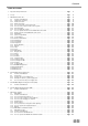
Contents Table of Contents 1. Important Safety Instructions . . . . . . . . . . . . . . . . . . . . . . . . . . . . . . . . . . . . . . . . . . . . . . . . . . . . . . . . . . . . . Page 7 2. Set-up . . . . . . . . . . . . . . . . . . . . . . . . . . . . . . . . . . . . . . . . . . . . . . . . . . . . . . . . . . . . . . . . . . . . . . . . . . . . . . . . Page 8 3. MCS-D 200 Control Unit . . . . . . . . . . . . . . . . . . . . . . . . . . . . . . . . . . . . . . . . . . . . . . . . . . . . . . . . . .
04 E
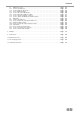
Contents 7.3 7.3.1 7.3.2 7.3.3 7.3.4 7.3.5 7.3.6 7.3.7 7.4 7.4.1 7.4.2 7.4.3 7.4.3.1 7.4.4 7.4.5 7.4.6 7.4.7 MCS-D 3171 / 3173 . . . . . . . . . . . . . . . . . . . . . . . . . . . . . . . . . . . . . . . . . . . . . . . . . . . . . . . . . . . . . . . Page Controls and indicators . . . . . . . . . . . . . . . . . . . . . . . . . . . . . . . . . . . . . . . . . . . . . . . . . . . . . . . . . . . . Page How to display the Device ID . . . . . . . . . . . . . . . . . . . . . . . . . . . . . . . . . . . . . .
Introduction Thank you for selecting the digital multimedia-based MCS-D 200 conference system from beyerdynamic. Please take some time to read carefully through this manual before setting up the equipment. This manual describes the installation and operation of the MCS-D 200 system without the control and configuration via PC. MCS-D 200 is a fully digital multimedia-based conference system in single-cable design. It can be used for small and large events in permanent installations or for mobile use.
Safety Instructions 1. Important Safety Instructions Control Unit and Power Supply Units • • • • • • • • • • • • • • • • • • • • • • • • • • • • • • • • READ these instructions. KEEP these instructions. HEED all warnings. Follow all instructions. Do not use this apparatus near water. Clean only with a dry cloth. Do not block any ventilation openings. Install in accordance with the manufacturer’s instructions.
MCS-D 200 Control Unit 2. Set-up The MCS-D 200 system may only be installed by staff acquainted with the appropriate safety instructions. The MCS-D 200 control unit and the power supply units have been developed for installation on tables or 19"-mounting. Do not cover the ventilating grille. When setting up the system please follow the safety instructions mentioned in chapter 1. Furthermore, please note • • • • • • the ambient temperature of the installation site must not exceed 50 °C.
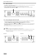
MCS-D 200 Control Units Rear view 13 11 13 20 14 16 17 18 19 15 12 11 Mains connection with fuse (6.3 A short-circuit protection) 12 NetRateBus conference sockets, MCS-D 200 with 1 Push-Pull socket to connect other power supply units for example. 13 Fan outlet (number of fan outlets depends on the number of power supply units integrated into the control unit) 14 RS 232 C (1). 9-pin Sub-D connection for PC or media control system.
MCS-D 200 Control Unit 3.2.2 Mains connection • Verify that the voltage rating of the unit matches that of the AC mains outlet you are to use. If you connect the unit to the wrong voltage, you may seriously damage it. • Always route cables running to the unit where they will not be damaged by heavy or sharp objects. • Connect the MCS-D 200 control unit to the mains 11 . The internal power supply unit of the control unit can adjust automatically between 100 V and 240 V at 50 - 60 Hz. 11 3.2.
MCS-D 200 Control Unit 3.2.4 How to connect a PC or media control system • If you would like to connect a PC or media control system to the MCS-D 200 control unit, use the RS 232 connection 14 or 15 . • In order to connect a PC use a standard RS 232 cable, straight - no null modem cable. If you connect other devices, please observe the pin assignment. • The system is configured via the MCS-D 200 control unit, please refer also to chapter 3.3 “How to operate the menu of the MCS-D 200 control unit”. 14 3.
MCS-D 200 Control Unit 3.3 How to operate the menu of the MCS-D 200 control unit • You can scroll through the menu by using the navigator buttons 8 and menu buttons 9 . 8 9 3.3.1 Menu overview of the MCS-D 200 control unit MAIN MENU SESSION [01] MAIN MENU* SESSION [02] MAIN MENU* SESSION [03] SYSTEM SETUP MENUS 1. Session 1.1 Modes/Limits 1.2 Channel List 1.1.1 Free 1.1.2 Request 1.1.3 Auto-Free Auto Request 1.3 President(s) 1.4 Interpreter 1.3.1 Set President(s) 1.4.
MCS-D 200 Control Unit 3.3.2 Main menu The main menu displays: the session number (here it is session 01), the current operating mode (here it is: Free), the number of open microphones (here the limit is: 3) and the volume of the loudspeakers of the microphone station (here it is -1.5 dB) MultiSession: How to change to the next meeting In the MultiSession operation, i.e.
MCS-D 200 Control Unit 3.3.3 System set-up menus Warning: In systems using PC and iCNS software the settings are operated via the iCNS software. The set-up menus of the MCS-D 200 control unit cannot be operated to avoid conflicts. Press the SETUP buttons to access the SYSTEM menus. The arrow indicates the current line. Scroll through the menus by using the up or down navigator buttons. Press the ENTER button to access the submenus.
MCS-D 200 Control Unit Use the up or down navigator button for scrolling. Warning: In systems using PC and iCNS software the settings are operated via the iCNS software. The set-up menus of the MCS-D 200 control unit cannot be operated to avoid conflicts. NO SESSION: iCNS is in the offline mode (conference closed), not in the online mode (conference started).
MCS-D 200 Control Unit 3.3.4 Session menus In the SESSION menus settings for the meeting such as Mode/Limit, Channel List, Presidents, Interpreters are selected for the meeting selected in the main menu. press the ENTER button Use the up or down navigator button for scrolling.
MCS-D 200 Control Unit 3.3.4.1 Mode / Limit menus In the MODES/LIMITS menu you can enter the operating mode and number of open microphones (limit) for the selected session (here it is session 01). press the ENTER button Free Mode Each delegate can turn on the microphone of the microphone station if the selected number of open microphones (limit) is not exceeded. Limit - Free Determine the maximum number of open microphones. The maximum number is 16.
MCS-D 200 Control Unit How to set Modes To select the mode press the SET button. A star in brackets indicates the selected operating mode. Session number Use the up or down navigator button for scrolling.
MCS-D 200 Control Unit How to set the Limits Press the LIMIT button to set the limit. Select the limit by using the right or left hand navigator buttons. Press the MODE button to return to the MODE menu. Change LIMIT: Press the left or right hand navigator button. Use the up or down navigator button for scrolling. Cursor is flashing Session number Press MODE button to return to the MODE menu.
MCS-D 200 Control Unit 3.3.4.2 Channel List In the menu CHANNEL LIST you can prepare and edit a list of all required channels. All channels have to be defined in the menu DEFINE CHANNELS (refer also to the chapter 3.3.5 “Define Channels”), because the channel list is basing on the predefined channels. Whenever the delegate presses the language/channel selector button of his microphone station, the list is displayed.
MCS-D 200 Control Unit When the NAME button is pressed, the cursor goes to the channel description (refer to illustration). The description can be changed as described in the following: Note: 1. By pressing the right or left hand navigator buttons you can assign a code of the international language list to a language channel (refer to chapter 11. “List of Language Codes”). 2. For other channels you can create another description with a maximum of three characters from a predetermined list.
MCS-D 200 Control Unit 3.3.4.3 President(s) In the PRESIDENTS menu you can assign the functions of a chairman station such as CANCEL, PRIORITY, PREVIOUS or NEXT to any microphone station in the selected session (here: session 01). press the ENTER button The following items refer to chairman stations: • Each chairman can turn on his microphone at any time, regardless of the selected limit. • Any number of microphone stations can be programmed as chairman stations.
MCS-D 200 Control Unit PRIORITY LEVEL(S) for Chairman Stations The arrow indicates the active line. session number Use the right or left hand navigator button to change the level press the ENTER button Device ID Level 0-99 Use the up or down navigator button for scrolling All microphone stations which have been programmed as chairman stations in the SET PRESIDENT(s) menu are listed here. You can assign a level to each chairman station. “0” is the highest level, “99” the lowest.
MCS-D 200 Control Unit 3.3.4.4 Interpreter In the INTERPRETER menu you can prepare a list of all required interpreter’s channels from the list of session channels for the selected session (here: session 01) (refer also to chapter 3.3.4.2 “Channel List”). The list includes only channels required for interpreters, i.e. all channels for the preselection of the relay and output channels.
MCS-D 200 Control Unit How to select the required interpreter’s booth(s) for the session Select all booths required for the selected session from the booth list (refer to chapter 3.3.7.1 “ID List”). The arrow indicates the active line. Session number press the ENTER button Use the up or down navigator button to scroll through the menu Booth number The star identifies the selected booth. Use the up or down navigator button to select the booth required for the session (here: 01).
MCS-D 200 Control Unit 3.3.5 Define Channels In the DEFINE CHANNELS menu all channels required for the whole system are defined, added or removed. By using these defined channels the lists of the session channels are prepared for the individual sessions (refer to chapter 3.3.4.2 “Channel List”). Note: • The OR channel does always exist in the list and may neither be edited nor deleted. • A channel currently in use may neither be edited nor deleted.
MCS-D 200 Control Unit For a language channel select the name from a list of international language codes (refer to chapter 11.
MCS-D 200 Control Unit 3.3.6 Options Use the up or down navigator button for scrolling press the ENTER button 3.3.6.1 Time In the TIME menu the system time for the MCS-D 200 control unit, MCS-D 202 and MCS-D 2073 microphone stations can be set manually (refer to chapter 7.1.6 “Menu settings”) in the format HOURS – MINUTES – SECONDS. When the iCNS software is started, the system time is refreshed automatically.
MCS-D 200 Control Unit 3.3.6.2 Ports The RS-232C(1) Port system. 14 and RS232C(2) Port 15 are configured to connect to a PC with the iCNS software or to a media control Press the up or down navigator button to select a COM port Use the right or left hand navigator button to scroll through a configuration list Use the up or down navigator button to go to COM 1 or COM 2. Use the right or left hand navigator button to scroll through the configuration list. 3.3.6.
MCS-D 200 Control Unit 3.3.7 Delegate IDs For identifying a device identification number (ID) should be assigned to each delegate station. Basically, the system can be operated without the organisation of ID numbers. But for special functions such as functions of a chairman station, phoning and some data bank manangement functions the organisation of the IDs of the microphone stations is absolutely necessary for a smooth meeting. In order to avoid conflicts each ID number can be assigned only once.
MCS-D 200 Control Unit 3.3.7.1 ID List You may assign an ID to individual devices. Also refer to chapter 3.3.7.2 “Set IDs” to find out how you can set IDs for all microphone stations. Use the right or left hand navigator button to edit the number press the ENTER button Use the up or down navigator button for scrolling Group number Device Identification number (ID) Hash indicates that the ID number has been already assigned to another device.
MCS-D 200 Control Unit 3.3.7.2 Set IDs This function allows you to set identification numbers for all microphone stations by pressing the MIC button of all microphone stations one after the other. The arrow indicates the active line Use the right or left hand navigator button to enter the first ID number. press the ENTER button Use the up or down navigator button for scrolling Device identification number Go to the “Group” line.
MCS-D 200 Control Unit 3.3.8 Interpreter IDs For identifying a device identification number (ID) should be assigned to each intepreter station. Basically, the system can be operated without the organisation of ID numbers. But for special iCNS software and service monitoring functions the organisation of the IDs of the interpreter stations is absolutely necessary for a smooth meeting. The ID number for an interpreter station consists of the booth ID and device ID.
MCS-D 200 Control Unit 3.3.8.1 Interpreter ID List You may select an individual device and assign a booth in combination with a device dentification number (DEVICE ID). Also refer to chapter 3.3.8.2 “Set Interpreter IDs” to find out how you can assign identification numbers to all interpreter stations.
MCS-D 200 Control Unit Go to the “Booth” line and enter the booth number. Then use the down navigator button to go to the “Device ID” line. Use the right or left hand navigator button to enter the first interpreter station ID number. Then press the MIC button of the first interpreter station to assign the first ID number to this microphone station. The LED ring will illuminate and the ID number will be shown on the display of the microphone station.
MCS-D 200 Control Unit 3.3.10 DAI/DDI Management The MCS-D 200 control unit features an integrated D/A interface (=INTERNAL DAI) with the connexions CH1 IN, CH2 IN, CH1 OUT and CH2 OUT. To provide more analogue inputs and outpus, additional Digital / Analog Interfaces (DAI) are connected via the conference bus for the connection of external audio devices such as wireless microphones or tape recorders providing the sound of a video film in different languages.
MCS-D 200 Control Unit 3.3.10.1 Ext. DAI ID List In the Ext. DAI ID LIST menu you may enter a device identification number (logical address) for every interface unit (=EXTERNAL DAI), that is an interface unit with 2 CH IN and 2 CH OUT each. Each interface unit is regarded as an independent device, even if there is a maximum of 3 interface units in the same 19" housing of one DAI. The interface units are recognised when the system is started.
MCS-D 200 Control Unit External DAI no. 01 press the ENTER button, to assign channels to DAI no. 01 Each DAI unit features CH1 IN, CH 2 IN; CH 1 OUT, CH 2 OUT Use the up or down navigator button for scrolling press the ENTER button for CH 1 OUT Use the right or left hand navigator to scroll through the list of defined channels! Scroll through the list of channels which has been defined in the DEFINE CHANNELS menu before. press the ADD button Press the ADD button to confirm the selected channel.
MCS-D 200 Control Unit 3.3.10.3 DAI Control The DAI CONTROL is operated as described in the following: • Switch on/off all LINE INPUTS and LINE OUTPUTS of the internal and external DAIs. Warning: Unused DAI inputs must be OFF, to avoid noise! • Adjust the level of all LINE INPUTS and LINE OUTPUTS of the internal and external DAIs INTERNAL DAI level EXTERNAL DAI level IN: -28.5 dB…+18 dB IN: -9.5 dB…+13 dB OUT: -78 dB…+16.5 dB OUT: -24 dB…+22.
MCS-D 200 Control Unit press the ENTER button for CH 1 OUT How to switch off a channel: Warning: Unused DAI inputs must be OFF, to avoid noise! press the OFF button How to switch on a channel: press the ON button How to set the level: INTERNAL DAI level EXTERNAL DAI level IN: -28.5 dB…+18 dB IN: -9.5 dB…+13 dB OUT: -78 dB…+16.5 dB OUT: -24 dB…+22.
CA 4115/30/45 Power Supply Unit 4. CA 4115/30/45 Power Supply Unit The MCS-D 200 control unit features a modular power converter for approximately 15 microphone stations (MCS-D 202 or MCS-D 2073); optionally two power converters for approximately 30 microphone stations. If the system is to be extended, you will require additional power supply units. The following power supply units are supplied for installation into a 19" rack. CA 4115 power supply unit (1 modular power converter = 2 A) for approx.
CA 4115/30/45 Power Supply Unit 4.2 Connection 4.2.1 Control unit – power supply unit • The MCS-D 200 control unit and the power supply unit are connected via the NetRateBus socket 8 . Refer also to chapter 8. “Set-up examples”. Warning: Connected devices (e.g. adapters or Digital/Analog interfaces) are powered by the MCS-D 200 control unit and have to be considered in power calculations. • Each unit which is connected to a NetRateBus socket is powered by the MCS-D 200 when it is switched on.
CA 4522/44/66 Digital/Analogue Interface 5. CA 4522/44/66 Digital / Analogue Interface (DAI) You may connect additional Digital / Analogue Interfaces (DAI) via the conference bus for the connection of external audio devices such as wireless microphones or tape recorders providing the sound of a video film in different languages. The 19" housing of a Digital / Analogue Interfaces (DAI) may be equipped with up to 3 interface units (=EXTERNAL DAI), each with 2 analogue audio inputs and outputs.
CA 4522/44/66 Digital/Analogue Interface Rear view 4 5 6 7 8 4 CH1 IN: XLR LINE IN input (female), ±0 dBm, balanced. The signal fed in will be transmitted to the loudspeakers of the microphone stations or to any other output which can be selected via the MCS-D 200 control unit. 5 CH2 IN: XLR LINE IN input (female), ±0 dBm, balanced. The signal fed in will be transmitted to the loudspeakers of the microphone stations or to any other output which can be selected via the MCS-D 200 control unit.
CA 4577 Digital/Digital Interface 6. CA 4577 Digital / Digital Interface (DDI) To provide digital AES/EBU outputs you may connect additional CA 4577 Digital / Digital Interfaces via the conference bus. The CA 4577 is powered via the system and will be recognised when the system is started. Use the DAI/DDI MANAGEMENT menus to adjust the following: • Assign channels to digital outputs The DDIs are operated as described in the following: • Switch on/off channels of all outputs 6.
MCS-D 2073 Microphone Station 7. Microphone Stations For the MCS-D 200 system there is a variety of microphone stations available. Make sure that the microphone and all cables are tightly and properly connected. If a cable is not properly connected, interferences can occur. All settings of the microphone stations are stored when the system is turned off. Standard settings can be reloaded via the MCS-D 200 control unit. 7.
MCS-D 2073 Microphone Station 1 Microphone socket. Make sure that the microphone is connected properly and tightly. 2 Loudspeaker. The original sound of the conference is transmitted via the two loudspeakers. When the microphone is activated, the loudspeaker of the microphone station is turned off automatically. 3 Headphone socket (3.5 mm TRS jack) on the right and left hand side (optional with a 2nd language selector).
MCS-D 2073 Microphone Station 7.1.2 How to turn the microphone on Press the microphone button 4 once to turn on the microphone or to enter a request-to-speak. Press the microphone button once again to turn off or cancel the request-to-speak. • The LED ring of the microphone will illuminate when the microphone is turned on. • The LED ring of the microphone will flash when a request-to-speak has been entered. The request-to-speak will be registered and the microphone unit will be released by the chairman.
MCS-D 2073 Microphone Station 7.1.3 How to set the volume of the headphone Press the left or right hand button 5 to set the volume of the connected headphone. The buttons feature an autorepeat function. Please make sure that the MENU button is not activated! When the MENU button is activated these buttons act as navigator buttons. When the value is set, the value (0 - 63) is displayed. The settings remain stored even when the system is turned off. 7.1.
MCS-D 2073 Microphone Station 7.1.6 Menu settings Activate the MENU button. The blue LED will illuminate. The time menu (CLOCK) is displayed. Select a menu with the navigator buttons Use the UP or DOWN button to select one of the following menus: CLOCK as default display The default display is only shown, when the display is not needed to show any other function. Format: HOUR – MINUTES – SECONDS. In the TIME menu of the MCS-D 200 control unit, the system time can be set manually.
MCS-D 2073 Microphone Station Telephone Note: If chip cards are used for the activation of the microphone stations, the participant himself can only dial when the chip card is inserted. When microphone stations are locked, the participants cannot dial, but accept phone calls. DEFAULT DISPLAY (e.g. CLOCK) TEL. 12-33-17 press the MENU button and select TEL. with the navigator buttons! press TEL.
MCS-D 2073 Microphone Station 7.1.7 How to switch on a microphone while phoning While phoning, the microphone of a microphone station can also be switched on or registered by pressing the microphone button. 1. If the microphone of a phoning participant is turned on, the phone call is interrupted immediately. The LED ring of the microphone is illuminated. The other participant will hear an engaged signal which can be turned off by pressing the MENU or ENTER button. 2.
MCS-D 2073 Microphone Station 7.1.10 MCS-D 2073 as chairman station Each MCS-D 2073 microphone station can be configured as a chairman station via the MCS-D 200 control unit. Refer also to chapter 3.3.4.3 “President(s)“. Note: Whenever the MENU button is activated, the PRIOR and CANCEL buttons cannot be enabled. When the MENU button is deactivated, the PRIOR and CANCEL buttons can be enabled once again. The chairman can control the discussion with the following function buttons: PRIOR.
MCS-D 3121 / 3123 Microphone Stations 7.2 MCS-D 3121 / 3123 The MCS-D 3121 delegate station provides one microphone button and a two-way loudspeaker with two tweeters. The MCS-D 3123 chairman station features one microphone button, a two-way loudspeaker with two tweeters as well as “Clear” and “Priority” buttons. 7.2.
MCS-D 3121 / 3123 Microphone Stations Lateral view MCS-D 3121 and MCS-D 3123 left hand side right hand side 2 2 8 1 Microphone 2 LED strip illuminates when the microphone is activated. 3 Loudspeaker. The original signal of the conference is transmitted via the loudspeakers. As soon as the microphone is activated the loudspeaker will be deactivated. The volume is set via the control unit. 4 Microphone button to activate the microphone.
MCS-D 3121 / 3123 Microphone Stations 7.2.2 How to turn on the MCS-D 3121 Press the microphone button 4 once to turn on the microphone or to enter a request-to-speak. Press the microphone button once again to turn off the microphone or to cancel a request-to-speak. • The LED of the microphone button and the LED strip 2 will illuminate when the microphone is activated. • The LED of the microphone button and the LED strip 2 will flash when a request-to-speak is entered.
MCS-D 3121 / 3123 Microphone Stations 7.2.3 How to operate the MCS-D 3123 chairman station By using the following function buttons, the chairman can conduct a meeting actively: “Prior” button The “Prior” button 6 operates only, if the microphone station has been programmed as a chairman station via the MCS-D 200. For a brief interruption or announcement the “Prior” button must be held down. If the microphone was turned off, it will be turned on by pressing the “Prior” button.
MCS-D 3171 / 3173 Microphone Stations 7.3 MCS-D 3171 / 3173 The MCS-D 3171 delegate station provides an LC display, one microphone button, five voting buttons and a two-way loudspeaker with two tweeters. The up / down navigator buttons allow selecting the desired channel while the headphone volume is set by using the right / left navigator buttons. In addition to the above mentioned features the MCS-D 3173 chairman station provides a “Clear” and a “Priority” button. 7.3.
MCS-D 3171 / 3173 Microphone Stations Bottom view MCS-D 3171 H and MCS-D 3173 H 11 11 Lateral view MCS-D 3171 and MCS-D 3173 left hand side right hand side 2 2 12 1 Microphone 2 LED strip illuminates when the microphone is activated. 3 Loudspeaker. The original signal of the conference is transmitted via the loudspeakers. As soon as the microphone is activated the loudspeaker will be deactivated. The volume is set via the control unit. 4 Microphone button with LED to activate the microphone.
MCS-D 3171 / 3173 Microphone Stations 7.3.3 How to display messages If a message is sent by using the iCNS software, it will appear in the LC display 5 of the appropriate microphone station. In the second line the message “Press Yes” will be displayed. This means the “Yes” button of the five voting buttons 6 has to be pressed to delete the messsage. During a voting pressing the “Yes” button the first time deletes the message; pressing the “Yes” button a second time means voting with “yes”. 7.3.
MCS-D 3171 / 3173 Microphone Stations FIFO - limit is not yet achieved: FIFO - limit is exceeded: LED of the microphone button and the LED strip will illuminate -> Microphone is turned on LED of the microphone button of the new speaker will illuminate -> Microphone of the new speaker is turned on -> Microphone of the speaker who has been speaking the longest is turned off, as soon as the new speaker turns on his microphone 7.3.
MCS-D 202 Interpreter Station 7.4 MCS-D 202 The MCS-D 202 is an interpreter station for one interpreter. It can directly be integrated into the conference network without an additional control unit. The access to the audio channels can be configured according to the application. The interpreter station can be operated with a gooseneck microphone or headset. 7.4.
MCS-D 202 Interpreter Station 1 Socket (DIN 45326) to connect a headset or gooseneck microphone. 2 Monitoring loudspeaker (2-way-loudspeaker system) reproduces the original signal. The loudspeaker is automatically muted as soon as the microphone is activated.
MCS-D 202 Interpreter Station 7.4.2 How to program the relay channel buttons 1-3 How to select the relay language channel (PRE-SELECT) Press the left or right hand PRE SELECT button to scroll through a list of all available relay channels without changing the pre-selected channels! The list is displayed in the top line. The language channels are coded according to the international language codes. When the PRE SELECT button is released, the system time is displayed in the top line of the display.
MCS-D 202 Interpreter Station 7.4.3 Output channels A and B Each interpreter station has two buttons for the output channels A and B. The interpreter can directly switch from output A to B, and vice versa. Both channels may be pre-selected. With the PRE SELECT buttons you can select a free output channel. “A” is the default output channel which is automatically defined when the system is started. Press the appropriate output channel button to select channel A or B; the appropriate LED will illuminate.
MCS-D 202 Interpreter Station 7.4.4 Call buttons TECH button Use the TECH button to contact the technician. Hold down the button while speaking or listening to the technician. Note: Only the interpreter can contact the technician, not vice versa. During the connection the following message will be shown on the right hand side of the display of the MCS-D 202 interpreter station: The ID number of the technician station will appear when pressing the TECH button, provided the technician is available.
MCS-D 202 Interpreter Station PRESIDENT button Use the PRESIDENT button of the MCS-D 202 interpreter station to contact the chairman. Hold down the button while speaking or listening to the chairman. Note: Only the interpreter can contact the chairman, not vice versa.
MCS-D 202 Interpreter Station 7.4.5 How to assign the interpreter ID Each interpreter station should be specified with an identification number (ID) in order to render an address. This may be done via the INTERPRETER IDs menu of the MCS-D 200 control unit (refer also to chapter 3.3.8 “Interpreter IDs”). Optional, the identification numbers may directly be assigned at each interpreter station one after the other. This way, you will always have an overview of the system, especially of large systems.
MCS-D 202 Interpreter Station How to set the ID The “SET ID” line is displayed. Station ID= BOOTH-ID + DEVICE-ID By using the PRE-SELECT buttons you can change the BOOTH ID and the DEVICE ID as described below: 1. BOOTH ID: press left/right relay channel PRE SELECT button 2. DEVICE ID: press left/right output channel PRE SELECT button 1. Change BOOTH ID 2. Change DEVICE ID Exit Save How to save the ID Press the MUTE button. The interpreter station ID is saved. The ID is shown on the left display.
MCS-D 202 Interpreter Station 7.4.6 How to save settings on a chip card The following settings can be saved on a chip card after the languages have been programmed (refer to “How to program the relay channel buttons 1-3” and “How to program the output channels A and B”). • Relay channel 1-3 with the channel that is transmitted via headphones whenever the REL/OR switch is switched to REL (arrow marks the channel).
MCS-D 202 Interpreter Station E 71
System Setup 8. Examples Single-sided powering of the microphone stations which are set up as a branch Please calculate the maximum cable length. We recommend using our standard cables. OK MCS-D 200 Inserting devices at any location Devices such as microphone stations, interpreter stations and digital / analogue interfaces are inserted at any location of the system.
System Setup Additional power supply units for branches MCS-D 200 control unit (1 integrated power supply = 2 A) . . . . . . . . . . . . . . for approx. 15 devices MCS-D 200 control unit option A (2 intergrated power supplies = 4 A). . . . . for approx. 30 devices To expand the system: CA 4115 power supply unit (1 integrated power supply = 2 A) . . . . . . . . . . . for approx. 15 devices CA 4130 power supply unit (2 integrated power supplies = 4 A) . . . . . . . . . . for approx.
System Setup Setup of the microphone stations in a circle With redundancy i.e. powering the microphone stations on both sides, any cable of the circle can be removed during operation without interrupting the meeting. All microphone stations are then powered on one side. In this way a microphone station can be replaced during operation for example. A condition for redundancy is that all cable lengths had been selected in a way that a single-sided powering could cover the power requirement.
System Setup Set up the microphone stations as a branch or in a circle. The microphone stations are connected to the Extension Ports of the power supply units as a branch or in a circle.
System Setup Do not link branches, which are powered by different power supply units! Warning: Never link branches, which are powered by different power supply units. This could lead to an overload of the cable and cause short circuits and cable fire.
System Setup How to connect a power supply unit to the Extension Port Note: In this setup the connected power supply unit no. 3 does only work when the power supply unit no. 2 is also turned on. MCS-D 200 1. CA 4115/30/45 power supply unit 2. CA 4115/30/45 power supply unit 3.
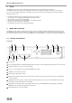
System Setup Setup of the system with microphone stations and interpreter stations 1 6 7 5 4 3 8 2a 9 2 1 MCS-D 200 control unit (push-pull socket) 2 MCS-D 2073 delegate station (push-pull sockets, 2 language selectors, 1 microphone, 2 headphones) 2a MCS-D 2073 delegate station as chairman station with PRIORITY and CANCEL buttons (configuration via MCS-D 200 control unit), 1 language selector, microphone and headphone 3 MCS-D 202 interpreter station, headset (or microphone and headphone) 4 CA 4145
System Setup System components Version with push-pull connections 1 MCS-D 200 control unit (with modular power supply for approx. 15, optional 30 microphone stations) 2 (Extension) CA 4115 power supply unit (1 modular integrated power supply = 2 A) CA 4130 power supply unit (2 modular integrated power supplies = 4 A) CA 4145 power supply unit (3 modular integrated power supplies = 6 A) 1 x for 1,400 delegate and interpreter stations.
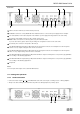
System Setup MultiSession Management All microphone stations in Session 1 OPERATOR 1 PC 6 7 8 5 SESSION 1 2a 4 80 E 2 3
System Setup 1 MCS-D 200 control unit (push-pull sockets) 2 MCS-D 2073 delegate station (push-pull sockets, 2 language selectors, 1 microphone, 2 headphones) 2a MCS-D 2073 delegate station as chairman station with PRIORITY and CANCEL functions (configuration via the MCS-D 200 control unit), 1 language selector, microphone and headphone 3 MCS-D 202 interpreter station, headset (or microphone and headphone) 4 CA 4145 power supply unit (6A) 5 CA 4566 digital / analogue interface (6 in/ 6 out) 6 CT 316 stationa
System Setup MultiSession Management OPERATOR 1 PC 6 7 8 5 2a SESSION 1 4 SESSION 2 SESSION 3 82 E 2 3
System Setup MultiSession Management: Several meetings can be simultaneously controlled by one MCS-D 200 control unit and the iCNS software. The individual conference rooms are combined to one large group (fig. 3b) or one large conference room (fig. 3a). For this only software settings are changed.
Accessories 9. Components MCS-D MCS-D MCS-D MCS-D MCS-D MCS-D MCS-D MCS-D MCS-D MCS-D 200 Digital control unit . . . . . . . . . . . . . . . . . . . . . . . . . . . . . . . . . . . . . . . . . . . . . . . . . . . . . . . . . . . . Order # 483.060 202 Interpreter station . . . . . . . . . . . . . . . . . . . . . . . . . . . . . . . . . . . . . . . . . . . . . . . . . . . . . . . . . . . . Order # 482.943 2073 Delegate/chairman station . . . . . . . . . . . . . . . . . . . . . . . . . . . . . . . . . . . .
Language Codes 11. List of Language Codes This is a list of language codes. You will find the web version under: http://lcweb.loc.gov/marc/languages/. Refer also to: http://www.ethnologue.com/iso639/codes.
Language Codes kab kac kal kam kan kar kas kau kaw kaz kha khi khm kho kik kin kir kmb kok kom kon kor kos kpe kro kru kua kum kur -kus kut Kabyle Kachin Kalâtdlisut Kamba Kannada Karen Kashmiri Kanuri Kawi Kazakh Khasi Khoisan (Other) Khmer Khotanese Kikuyu Kinyarwanda Kyrgyz Kimbundu Konkani Komi Kongo orean Kusaie Kpelle Kru Kurukh Kuanyama Kumyk Kurdish Kusaie Kutenai lad lah lam lao -lap lat lav lez lin lit lol loz ltz lua lub lug lui lun luo lus Ladino Lahnda Lamba Lao Sami Latin Latvian Lezgian Li
Technical Specifications tsn tso -tsw tuk tum tur tut tvl twi tyv Tswana Tsonga Tswana Turkmen Tumbuka Turkish Altaic (Other) Tuvaluan Twi Tuvinian uga uig ukr umb und urd uzb Ugaritic Uighur Ukrainian Umbundu Undetermined Urdu Uzbek vai ven vie vol vot Vai Venda Vietnamese Volapük Votic wak wal war was wel wen wol xho Wakashan languages Walamo Waray Washo Welsh Sorbian languages Wolof Xhosa yao yap yid yor Yao Yapese Yiddish Yoruba ypk Yupik languages zap zen zha znd zul Zapotec Zenaga Zhuang
Technical Specifications MCS-D 200 Control Unit Max. power consumption. . . . . . . . . . . . . . . . . . . . . . . 1 power supply: 2 A, approx. 137 W 2 power supplies: 4 A, approx. 255 W Input voltage . . . . . . . . . . . . . . . . . . . . . . . . . . . . . . . . . 100 - 250 V Supply voltage . . . . . . . . . . . . . . . . . . . . . . . . . . . . . . . . ±24 V, max. 2 A Fuse . . . . . . . . . . . . . . . . . . . . . . . . . . . . . . . . . . . . . . . . 6.3 A; slow-blow fuse System connections . . . . . .
Technical Specifications MCS-D 3121/MCS-D 3123 Microphone Station Frequency response. . . . . . . . . . . . . . . . . . . . . . . . . . . . 130 Hz - 17,000 Hz Microphone . . . . . . . . . . . . . . . . . . . . . . . . . . . . . . . . . . Line Array Pick up pattern . . . . . . . . . . . . . . . . . . . . . . . . . . . . . . . Corridor Current consumption . . . . . . . . . . . . . . . . . . . . . . . . . . 67 mA (microphone on) T.H.D. . . . . . . . . . . . . . . . . . . . . . . . . . . . . . . . . . . . . . .
Technical Specifications CA 4213/14 Adapter Connections CA 4213 . . . . . . . . . . . . . . . . . . . . . . . . . . . . . . . . . . . . . 3 x push-pull CA 4214 . . . . . . . . . . . . . . . . . . . . . . . . . . . . . . . . . . . . . 4 x push-pull Power supply . . . . . . . . . . . . . . . . . . . . . . . . . . . . . . . . via bus system Current consumption . . . . . . . . . . . . . . . . . . . . . . . . . . 65 mA Temperature range . . . . . . . . . . . . . . . . . . . . . . . . . . . .
Notes E 91
beyerdynamic U.K. Ltd. 17 Albert Drive Burgess Hill RH15 9TN Tel. +44 (0) 1444 258 258 Fax +44 (0) 1444 258 444 E-mail: sales@beyerdynamic.co.uk Internet: www.beyerdynamic.co.uk beyerdynamic Inc. USA 56 Central Ave. Farmingdale, NY 11735 Tel. +1 (631) 293-3200 Fax +1 (631) 293-3288 E-mail: salesUSA@beyerdynamic.com Internet: www.beyerdynamic.com E2/BA MCS-D 200 (04.07)/589.861 • Subject to change without notice. beyerdynamic GmbH & Co. KG Theresienstr. 8 D-74072 Heilbronn Tel.