
Installation Manual

LC / UPC / APC CONNECTORS TERMINATION
PROCEDURE / INSTALLATION
PRECAUTIONS:
• Safety glasses should be worn at all
times while performing the installation
procedures
• Avoid skin contact with epoxy or anae-
robic adhesive
• When the heater is in operation, place
it away from combustibles.
• Disconnected optical connectors may
emit radiation if the far end is coupled
with a working laser or Light-Emitting
Diode (LED). Do not view the ber
end of a cable or plug with an optical
instrument until absolute verication is
established that the ber is disconnec-
ted from any laser or LED source.
• For cleaning of this ber optic pro-
ducts, always use Beyondtech Isopropyl
Alcohol & lint-free wipes.
REQUIRED TOOLS AND MATERIALS:
• Scissors .
• Fiber Crimp Tool.
• Dual Hole Strip Tool.
• Cable Jacket Stripper.
• Strive Tool.
• Inspection Microscope.
• Oven .
• Epoxy / Anaerobic Adhesive .
• Beyondtech Lint Free Wipes.
• Isopropyl Alcohol.
• Marker.
• Lappin Films.
ASSEMBLY PROCEDURE:
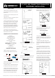
• Slide the boot, ring and junk ring
inside the Fiber cable see Figure Nº 1.
Boot
Ring
Connector Head
Dust Cap
• Remove the connector dust cover from
the connector head.
• Prepare epoxy or anaerobic adhesive
according to manufacture instruction.
• Apply to the connector head using a
syringe you should stop injecting epoxy
or anaerobic adhesive when the glue
forms a small bead at the top of the
connector ferrule review gure N°2.
Figure N ° 1
•
Mark the cable as shown in gure Nº 3.
• Using the cable jacket stripper, strip
the outer jacket to the second mark.
• Trim the aramid strength members
close to de the jacket. Be careful not to
break the ber review gure N° 5.
• Using the cable jacket stripper, strip
the outer jacket to the FIRST mark. It
should look like gure N° 6
• Using the dual holes strip tool strip
the ber completely until the ber core
appears, clean it with Beyondtech lint-
free wipes.
• Insert the bare ber though the
connector head with a twisting motion
until ber jacket buttons against the
ferrule.
• If using oven place the connector
assembly into one of the ports. Cure
for the time recommended for epoxy
supplier.
• Slide the junk and the ring towards
the connector head position and with
the crimp tool apply pressure onto the
assembly junk- ring-connector head .
• Slide the boot over the crimped area
of connector. Place the strive tool
directly above the ferrule and lightly
draw the beveled edge across the ber
Pull it straight away from the connector
to complete the cleaving operation.
Figure N ° 2
Figure N ° 4
Figure N ° 5
Figure N ° 6
Figure N ° 7
LC/ UPC / APC CONNECTORS TERMINATION PROCEDURE / INSTALATION PRO-
REV -01-2017
©2018 Beyondtech, Inc. All rights reserved. Beyondtech® is a trademark of Beyondtech, Inc. | www.beyondtech.global
LC Connector
Cover
Figure N ° 3