XS8 Elliptical OWNER’S MANUAL ASSEMBLY OPERATION WARRANTY MAINTENANCE PARTS ORDERING CAUTION: Exercise of a strenuous nature, as is customarily done on this equipment, should not be undertaken without first consulting a physician. No specific health claims are made or implied as they relate to the equipment. IMPORTANT: Read all instructions carefully before using this product. Retain this owner’s manual for future reference.
TABLE OF CONTENTS Attachment - A- Safety……………….….....1 Attachment - B - Training……………..........2 Parts & Hardware Contents………...... ........6 Pre-Assembly Instructions……......................8 Assembly Instructions…………………........9 Console Operations……………....................16 Maintenance…………………………............20 Exploded View ………....................................21 Parts List ………………….............................23 Warranty……..………………………............
ATTACHMENT - A IMPORTANT SAFETY ADVICE PRECAUTIONS This elliptical has been designed and constructed to provide maximum safety. Nevertheless, certain precautions should be taken when using exercise equipment. Read the whole manual before assembling and using the elliptical. The following safety precautions should also be observed: 1. Keep children or pets away from this equipment at all times. DO NOT leave them unsupervised in the room where this elliptical is kept. 2.
ATTACHMENT - B TRAINING GUIDELINES Exercise is one of the most important factors in the overall health of an individual. Listed among its benefits are: Increased capacity for physical work (strength endurance) Increased cardiovascular (heart and arteries/veins) and respiratory efficiency Decreased risk of coronary heart disease Changes in body metabolism, e.g. losing weight Delaying the physiological effects of age Physiological effects, e.g. reduction in stress, increase in self-confidence, etc.
ATTACHMENT - B (cont’d) Specifics Different forms of exercise produce different results. The type of exercise that is carried out is specific both to the muscle groups being used and to the energy source involved. There is little transfer of the effects of exercise, i.e. from strength training to cardiovascular fitness. That is why it is important to have an exercise program tailored to your specific needs.
ATTACHMENT - B (cont’d) The target is not a magic number, but a general guide. If you’re above average fitness, you may work quite comfortably a little above that suggested for your age group. The following table is a guide to those who are keeping fit. Here we are working at about 80% of maximum.
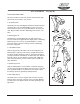
ATTACHMENT - B (cont’d) SUGGESTED STRETCHES 1 The correct form for several basic stretches is shown at the right. Move slowly as you stretch—never bounce. 1. Toe Touch Stretch Stand with your knees bent slightly and slowly bend forward from your hips. Allow your back and shoulders to relax as you reach down toward your toes as far as possible. Hold for 15 counts, then relax. Repeat 3 times. Stretches: Hamstrings, back of knees, and back. 2 2. Hamstring Stretch Sit with one leg extended.
PARTS & HARDWARES Mai m fram e Track S2(LEFT) E1(RIGHT) S1(RIGHT) E2(LEFT) Connect handle bar tube G1(RIGHT) G2(RIGHT) Connected with pedal tube(LEFT ) 6
PARTS & HARDWARES (cont’d) (K1)Water bottle (K2) Bottle holder N2(REAR) Decortation cover of pedal tube L1(R) N1(FRONT ) L2(L ) Decortation cover of handle bar R1 SCREW M8X58 R2 SCREW M8X70 Decortation cover of j ointed pedal tube R3 SCREW M8X20 P1(LEFT ) R4 SCREW M10X112 R5 SCREW M5X20 R6 SCREW M6X10 R7 SCREW M8X15 P2(RIGHT) R8 SCREW M8X20 BK R9 SCREW M4X15 R12 SCREW M5X10 R13 SPRING WASHER M8 R10 SCREW M4X10 R11 SCREW M8X20 BK R14 WASHER R2 2 NUT M8 R15 WASHER R23 WASHER TOOL R16 S
PRE-ASSEMBLY INSTRUCTION GENERAL INSTRUCTIONS Carefully read through the instructions contained in this manual. It provides you with important information about assembly, safety and use of the machine. 1. This unit has been designed for light commercial use. The weight of the user must not exceed 400 lbs. (181 kg.) 2. Keep your hands well away from any of the moving parts. 3.
ASSEMBLY INSTRUCTIONS ASSEMBLY FOR FRONT STABILIZER Secure the front stabilizer(B) to the main frame(A) using two screws(R4), two spring washers(R17) and two washers(R15). A R15 B R17 R4 ASSEMBLY FOR SLIDE TRACK A Put the moving wheel(F28) on the slide track(C). Then, secure the slide track to the main frame(A) using two screws(R1), two screws(R7), four spring washers(R13) and four washers(R14).
ASSEMBLY INSTRUCTIONS (cont’d) ASSEMBLY FOR CENTRAL SUPPORT TUBE & DECORATION COVER D Step1. Slide decorative cover(H) into center support tube(D) from the bottom. Step2. Connect the sensor(D2) with cable sensor(A2). R14 R13 R7 H D2-1 D2 A2 A2-5 Step3. Insert the center support tube onto the main frame(A). Then, secure them with bolts(R7), spring washers(R13) and washers(R14). A Step4. Slide the decorative cover down. ATTENTION: TAKE CARE NOT TO PINCH THE CABLES OR WIRES WHILE ASSEMBLING THE MACHINE.
ASSEMBLY INSTRUCTIONS (cont’d) BOTTLE HOLDER ASSEMBLY Attach the bottle holder(K2) to the center support tube with screws(R5). LEFT PEDAL SUPPORT TUBE ASSEMBLY K1 Step1. Place the roller of left pedal support tube(F) onto the slide track on the main frame Slide the pedal tube (F) into the bushing of the flywheel Then, secure it with screw(R11), spring washer(R16) and flat washer(R20). K2 R5 R20 R16 L2 R11 R10 F R18 R18 F2 F28 Step2.
ASSEMBLY INSTRUCTIONS (cont’d) R10 N1 R8 R16 R21 R23 R19 N2 R22 S2 R10 R2 R13 R14 F2 R12 P2 P1 R12 R9 F2 ASSEMBLY FOR LEFT SWING TUBE Step1. Insert the ring(R19) and washer(R23) into the center support tube. Step2. Attach the left swing tube(S2) to the center support tube with screw(R8), spring washer(R16) and flat washer(R21). Step3. Secure the connect tube(F2) with swing tube((S2) using screw(R2), flat washer(R14), spring washer(R13) and nut(R22). Step4.
ASSEMBLY INSTRUCTIONS (cont’d) ASSEMBLY FOR SIDE HANDLE BAR Step1. Insert the right handle bar(E1) into the right swing tube(S1). Then, secure them using flat washers(R14), spring washers(R13) and screws(R3). Step2. Insert the sensor wire(E1-1) of the right handle bar(E1) into the available sensor hole(D1-3) of the center support tube. E1 E2 E1-1 REPEAT STEP1 ~ STEP2 FOR THE LEFT HANDLE BAR S2 S1 R14 R13 D1-3 R3 J ASSEMBLY FOR HANDLE BAR Connect the sensor wires(G1-1) and (D1-2).
USE THE ADAPTOR M Place the machine near a wall outlet and plug in the adaptor. Plug in the other end of the adaptor (round plug) to the jack on the machine. MOVE THE MACHINE Handle Bar Transport Roller To move, pick the machine up at the end of the slide track and lift. Then, push or pull the machine on its rollers equipped on the front stabilizer.
ASSEMBLY INSTRUCTIONS (cont’d) 15
CONSOLE FUNCTION BUTTONS: MODE - To confirm all setting values. RESET - To reset all setting values. Hold on pressing for 2 seconds, monitor will resume to power-up mode. START/STOP - To start or stop training. When time count down to 0:00, the computer will stop automatically and beep for 8 seconds. Time will resume to pervious setting value. When user stop training by themselves, the computer will remain all the setting values and display heart rate chart UP - To make upward setting.
CONSOLE (cont’d) DISTANCE Count up – no preset target, distance will count down from 0.00 to 99.50. Count down – with preset target, distance will count up from preset to 0. PULSE The monitor will detect and display heart rate when user holds on to hand grip sensor or wears chest belt. If the user wears chest belt and holds on to the handgrips at the same time, the system will display the handgrip (priority) reading When the monitor cannot detect pulse signal, will display “P”.
CONSOLE (cont’d) TIME : when blinking, you may press UP or DOWN button to set up target training time from 00:00 to 99:00. Press MODE to confirm setting. DISTANCE : when blinking, you may press UP or DOWN button to set up target distance from 0.00~99.59. Press MODE to confirm setting. CALORIES : when blinking, you may press UP or DOWN button to set up target calories from 0~9990. Press MODE to confirm setting. PULSE : the monitor will detect user’s heart rate.
CONSOLE (cont’d) from 0.00~99.59. Press MODE to confirm setting. CALORIES : when blinking, you may press UP or DOWN button to set up target calories from 0~9990. Press MODE to confirm setting. PULSE : the monitor will detect user’s heart rate. Please hold on handgrip sensor or wear chest belt when start exercise. Press START button to start training: Screen display profile automatically according to the preset target Watt data, current RPM and training speed. This profile is not available to be adjusted.
MAINTENANCE INSTRUCTIONS CLEANING WARNING: Always unplug your elliptical prior to cleaning or servicing your unit, in order to avoid electrical hazard or shock. Care has been taken to assure that your elliptical has been properly adjusted and lubricated at the factory. It is not recommended that the user attempt service on the internal components instead seek service from an authorized service center.
EXPLODED VIEW A5 - 1 1 A5 - 9 A5 - 1 0 A5 - 1 3 A5 - 1 4 A1 1 A5 - 5 A5 - 1 2 A1 2 * 8 A5 - 8 A5 A5 - 7 A5 - 6 A4 A1 3 * 4 A5 - 2 A5 - 3 A5 - 9 A5-15 A5-4 A2 A3 A3 - 3 A3 - 1 A3 - 4 A1 A3 - 5 A1 0 A3 - 2 A2 - 1 A1 - 4 M A2 - 2 A2 - 3 A1 - 3 A1 - 1 A1 - 2 A1 2 -1 * 2 A1 - 5 A2 - 4 A9 - 2 A9 - 5 A9 - 1 * 2 A1 2 * 1 0 A8 A1 3 * 4 A7 A9 * 1 6 A9 - 4 A9 - 3 A6 A6 - 1 A6 - 2 21
22
PARTS LIST P/N Q’TY P/N DESCRIPTION DESCRIPTION Q ’T Y A MAI N FRAME 1 A8 CRANK (L) 1 A1 MAI N FRAME 1 A9 SCREW (M5* 20L) 16 1 A9-1 NUT (M10* P1.0) 2 1 A9-2 TURNI NG CONNECTOR 1 A1-1 Cross Head Screw for Axle A1-2 UPPER IRON (T=3.0) (M5*15L) A1-3 LOWER I RON (T=3.
PARTS LIST (cont’d) E1 SIDE HANDLE BAR( R) 1 F33 E1-1 SENSOR WIRE 1 E2 SIDE HANDLE BAR(L) 1 E2-1 SENSOR WIER 1 E3 SPONGE 2 G1 FRONT HANDLEBAR(RIGHT) 1 E4 TOGGLE SWITCH (RIGHT) 2 G1-1 HAND PULSE SENSOR WIRE 1 E5 TOGGLE SWITCH (LEFT) 2 G2 FRONT HANDLEBAR(LEFT) 1 E6 TOGGLE SWI TCH (UPPER) 6 G2-1 HAND PULSE SENSOR WIRE 1 E7 PLASTIC CIRCUIT BOARD 2 G3 HAND PULSE 2 E8 SCREW (M3-10L) 2 G4 PAD FOR HAND PULSE 2 F1 RIGHT MOVING HANDLE BAR 2 G5 HAND PULSE 2 F2 PE
WARRANTY USA / CANADA Warranty Warranties may vary in other countries. See your local BH Fitness Dealer. WARRANTY SUBMITTAL Please have the following information available when contacting your dealer or BH for warranty support. • A copy of the dated purchase receipt or credit card statement. • An explanation of the problem/malfunction or parts that are missing or damaged. • Owner’s name, address and phone number.
WARRANTY (cont’d) ELECTRONICS & PARTS – Home - Light Commercial / 5 Years BH Fitness warrants the Electronic components and all original parts against defects in workmanship and materials for a period of five years from the date of original purchase, as long as the device remains in the possession of the original owner.