
User`s manual

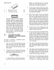
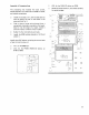


o Install capacitor
C1
near the
top
edge
of
the
board.
o Solder
C1
in place. Clip
excess
lead ends.
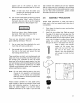
I WARNING I
Avoid eye
injury.
Hold lead ends
as
you
clip them
so
they
can't
fly
up
at
you.
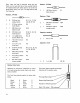
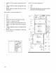
Assembly
of
TTY Interface
Area-
o
o
o
o
o
Install a 100 Ohm,
1/2
Watt resistor (brown-
black-brown)
at
R
1.
Install a 4.7k Ohm resistor (yellow-violet-red)
at R2.
Install a 1.6k Ohm resistor (brown-blue-red)
at
R3.
I nstall a 1 k Ohm resistor (brown-black-red) at
RI!.
Install a 47 Ohm resistor (yellow-violet-black)
at R5.
o Install a 2.7k Ohm resistor (red-violet-red) at
R6.
o Solder the six resistors in place, then clip
their
excess
lead ends.
o Install a 1
uf
capacitor at C5, and solder and
clip it.
o Install a 200 Ohm, 1 Watt resistor (red-black-
brown) at R34.
2-8
":.,
I'~-=~
~':~~':::"
:~~l
::f:~~;t:.;:.-,~,,~
I
o
~W{;f~,tF
+Em~~"
GND
ERS
_______
-,
J7
A3
,
,,~
(9
,~
. I
''''t:nr'''l..t:
I
C
_.
__
. .,
~ol
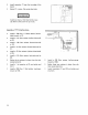
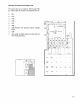
o Install a
430
Ohm resistor (yellow-orange-
brown) at R35.
o Solder these
two
resistors in place, then clip
their
excess
lead
ends.
o Install transistors 01 and
02,
and solder and
clip them.