
Product Warranty


17
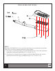
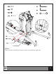
STEP 3
Insert Left Connection Tube (P-1) until the top part of Left Handle Connection Tube (C)
aligns with mating spindle and insert as shown below.
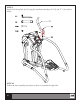
STEP 4
Insert the Left Connection Tube (P-1) into Main Frame Set (A) until it seats. You may have
to tap the Left handle connection tube (C) with a rubber mallet in order to seat all the way
as shown below.
STEP 5
Make sure the 8 fastener holes are lined up, then use attachment hardware V-9 (6) for the six
lower holes and V-10 (2) and V-11 (2) hardware in step 3 for the remaining two upper holes.
e top part of Left Handle Connection
Tube (C) aligns with mating spindle.
Fasten using attachment hardware V-10
(2) and V-11(2).
8 fastener holes.
Seated all the way in.
Tap with a rubber mallet here.
STEP 6
Follow the same assembly procedures as above to assemble the Right side.