
Owner`s manual


15
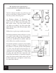
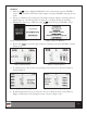
For the next stage of the assembly, it is recommended
to lower the platform back on the oor, with the
help of a second person. Take the handlebar (4) as
shown in Figure 3, and line up the holes. Fit the
screws (29) and at washers (16) and use the 6mm
Allen Wrench to tighten securely. It is possible that
the hand straps (17) may have come loose during
shipment. Fit them back into place (as shown in
Figure 4).
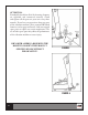
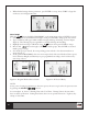
START-UP
Plug the power cord (35) into the vibration machine
on the column, see Figure 5, and then the other
end of the cord into an electrical outlet (110V). Set
switch (L) to the on position (I), Figure 5. Note:
A mechanical knocking noise is normal when the
vibration motors rst begins to run, this will stop as
soon as the motor reaches working speed. Similarly,
when the motor is switched o, you will also hear this
knocking noise as the motor slows down, but it will
stop as soon as the motor is at a standstill.
TRANSPORT & STORAGE
e vibration machine is equipped with wheels
(see #40 in Figure 6), to make it easier to move.
Make sure that the power cord is unplugged from
the electrical outlet before moving the vibration
machine. To prevent accidents DO NOT move the
platform across uneven oors.
INSPECTION & MAINTENANCE
Switch the vibration machine o and unplug the
power cord. Use a damp cloth or towel to clean the
dust o the platform, especially the handrails and
the electronic console. Do not use solvents.
FIGURE 3
FIGURE 4
16
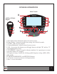
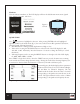
Auxiliary
Column
Keypad
Auxiliary
Column
Keypad