
System information
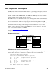
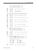
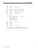
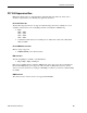
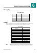
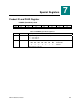
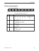
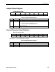
Table Of Contents
- Introduction
- Configuration and Setup
- Physical Details
- System Features
- Interfaces and Connectors
- Utility I/O Connectors
- IDE
- SATA Ports
- Serial Ports
- Parallel/Floppy Port
- PS/2 Keyboard and Mouse
- USB
- CompactFlash
- Programmable LED
- External Speaker
- Push-Button Reset
- Video Interface
- Ethernet Interface
- CPU Temperature Monitor
- Audio
- Watchdog Timer
- Analog Input
- Digital I/O
- SPI Interface
- PWM Outputs and TACH Inputs
- PC/104 Expansion Bus
- System Resources and Maps
- Special Registers
- Appendix A – References

Interfaces and Connectors
EBX-22 Reference Manual 65
SPI “BIT BANG” MODE
A special register is available at 1D7h, which enables the direct control (“bit banging”) of the SPI
interface. To use this register, the SPI field (bits D6-D5) of the MODCON register (1DFh) must
be set to 0h (see Table 44 for mode control settings).
SPIBB (Read/Write) 1D7h
D7 D6 D5 D4 D3 D2 D1 D0
SPI_IN SPI_INT SPI_CLK SPI_OUT SPI_CS3 SPI_CS2 SPI_CS1 SPI_CS0
Table 33: SPIBB Bit Assignments
Bit Mnemonic Description
D7 SPI_IN
SPI Input – This bit is read-only.
D6 SPI_INT
SPI Interrupt – This bit is read-only.
D5 SPI_CLK
SPI Clock – This bit is read/write.
D4 SPI_OUT
SPI Output – This bit is read/write.
D3-D0 SPI_CS
SPI Chip Select – These bits are read/write.