SPM522D Digitally Controlled Stereo Preamp/Mixer Operation Manual ® 5/26/98 Biamp Systems, 10074 S.W. Arctic Drive, Beaverton, Oregon 97005 U.S.A. (503) 641-7287 http://www.biamp.com an affiliate of Rauland-Borg Corp.
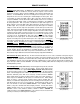
SPM522D TABLE OF CONTENTS Front & Rear Panel Features INTRODUCTION pgs. 2 & 3 Remote Controls pg. 4 Setup / Options pg. 6 Configuration - PC Control Software pg. 7 Computer Control pg. 15 Applications pg. 18 Block Diagram pg. 22 Specifications pg. 23 ® The ADVANTAGE SPM522D provides five stereo line inputs, two mono mic/line inputs, and two independent stereo outputs.
FRONT & REAR PANEL FEATURES zone main max ADVANTAGE SPM522D Stereo Preamp Mixer preset channel mic main zone min A B C D E F G H 1 2 3 4 5 1 Setup 2 mute Error (1) IR on (2)(3)(4) (5) (6) FRONT PANEL FEATURES (7) (4) IR Indicator: This red LED indicates when any information has been received via remote control (see Remote Controls on pg. 4). If the IR and Error LEDs flash simultaneously, this may be an indication of improper installation.
FRONT & REAR PANEL FEATURES (12) R an affiliate of Rauland-Borg Corp.
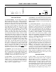
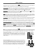
REMOTE CONTROLS The type and quantity of remote controls is optional for the SPM522D. Remote control affects source selections, preset selection, mic/line input levels, and main/zone output levels. Remote controls may be added at any time, and do not require the SPM522D to be modified, opened, or removed from a rack. There are five types of remote controls available: The Infrared Transmitter, the Infrared Receiver, the Wall-Mount Panel, the Remote Interface Kit, and the Remote Display Panel.
REMOTE CONTROLS Wall-Mount (Biamp #909-0074-00): The Wall-Mount is a "hard-wired" control, which is powered by the SPM522D. There are no batteries to wear out, and it is not easily lost or stolen. The wallmount may be wired up to 2000 feet from the SPM522D, using 2-conductor shielded cable (not included). To install Wall-Mount, first remove mounting box from front panel. Route cable through "knock-out" hole on rear of mounting box. Install mounting box in wall or panel.
SETUP / OPTIONS SETUP Setup Mode allows presets to be defined and stored in non-volatile memory, without the need to use the PC Control Software for Configuration via computer. Setup Mode may also be used to return the SPM522D to the factory default settings. To enter Setup Mode: While power is on, press and hold the front panel Setup button for 5 seconds (until the currently lit Front Panel Display LEDs begin flashing).
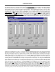
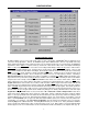
CONFIGURATION ® All Configuration parameters are adjustable using the Windows 95 'PC Control Software' and serial cable provided with the SPM522D. ® The PC Control Software provides programs for various ADVANTAGE products, including the SPM522D. The SPM522D program includes multiple control screens, which are described on the following pages. Factory default settings are shown on each screen.
CONFIGURATION TONE and BALANCE SCREENS Tone and Balance screens are available for all five Stereo Line Inputs. They are accessed through the Configure SPM522D drop-down menu (or by right-clicking on the Mix screen). Also, double-clicking on a Channel (1~5), within the Mix screen, will simutaneously select that channel and open its specific Tone and Balance screen.
CONFIGURATION BUTTON DEFINITION SCREEN ® The Button Definition screen is used to assign specific ‘actions’ to remote control buttons. ADVANTAGE infrared & wall-mount remote controls have twenty-eight buttons. However, the SPM522D supports twelve additional buttons, which are only available when using Remote Interface Kit or RS-232 control (see Remote Controls on pg. 5 & Computer Control on pg. 15).
CONFIGURATION REMOTE PORT CONFIGURATION SCREEN The Remote Port Configuration screen is accessed by opening the Button Definition screen and left-clicking on Remote Configuration. The Remote Port Configuration screen determines which types of actions will be recognized by each of the three possible remote control inputs on the SPM522D (see Button Definition on previous page). Remote 1 & Remote 2 refer to the corresponding terminals on the rear panel of the SPM522D (see Front & Rear Panel Features on pg. 3).
CONFIGURATION MISCELLANEOUS SCREEN The Miscellaneous screen is accessed by opening the Configuration Options screen and left-clicking the Miscellaneous tab. The Miscellaneous screen is used to select options which customize the operation of the SPM522D. At the top of the Miscellaneous screen, the Serial Number and Firmware Version of the particular SPM522D will be displayed. The PC Control Software can operate ‘off-line’ (with no product connected) by opening a ‘new’ file for the desired product.
CONFIGURATION MUTE 1 / MIC 1 SCREEN The Mute 1 / Mic 1 screen is accessed by opening the Configuration Options screen and left-clicking the Mute 1 / Mic 1 tab. The Mute 1 / Mic 1 screen is used to select options which customize the function of the Mic 1 Mute terminal (see Front & Rear Panel Features on pg. 2). Left-clicking Mute 1 input causes gated operation of Mic 1 toggles assignment of gating to the Mic 1 signal.
CONFIGURATION MUTE 2 / MIC 2 SCREEN The Mute 2 / Mic 2 screen provides the same functions as the Mute 1 / Mic 1 screen, except that it affects the Mic 2 Mute terminal instead. The Mute 2 / Mic 2 screen is accessed by opening the Configuration Options screen and left-clicking the Mute 2 / Mic 2 tab. The Mute 2 / Mic 2 screen is used to select options which customize the function of the Mic 2 Mute terminal (see Front & Rear Panel Features on pg. 2).
CONFIGURATION CHANNEL 5 OVERRIDE SCREEN The Channel 5 Override screen is accessed by opening the Configuration Options screen and left-clicking the Channel 5 Override tab. The Channel 5 Override screen is used to select options which customize the function of the Override terminal (see Front & Rear Panel Features on pg. 3). When Channel 5 Override is released, the previously selected Stereo Line Input for each output will again be selected.
COMPUTER CONTROL The SPM522D has an RS-232 compatible serial interface, which allows it to be controlled by a computer (see Rear Panel Features on page 3). In addition to the PC Control Software, the SPM522D offers two other methods of computer control. Control Button Emulation: This method allows the computer to emulate the operation of the infrared transmitter or wall-mount control panel.
COMPUTER CONTROL Serial Interface Electrical Connections & Cabling: The 9-pin Subminiature D (male) connector on the SPM522D rear panel provides the RS-232 compatible serial interface signals used for computer control. The SPM522D transmits serial data on pin 3 (TxD) and receives serial data on pin 2 (RxD). The serial interface ground is on Pin 5. The DTR & RTS signals are connected to the +12 Volt power supply (each through its own resistor) and are always asserted when the SPM522D power is on.
COMPUTER CONTROL SPM522D to PC 9-Pin Connector 9-pin SPM522D male n/a RxD TxD DTR ground n/a RTS n/a n/a female 1 2 3 4 5 6 7 8 9 1 2 3 4 5 6 7 8 9 n/a RxD TxD DTR ground n/a RTS n/a n/a female 1 2 3 4 5 6 7 8 9 1 2 3 4 5 6 7 8 9 1 2 3 4 5 6 7 8 9 #4 9-pin n/a RxD TxD DTR ground n/a RTS n/a n/a #3 1 2 3 4 5 6 7 8 9 These connections may not be required: DTR to CD; DTR to DSR; or RTS to CTS.
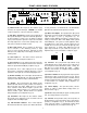
APPLICATIONS Retail Bookstore plus Music Department with Paging and Remote Control music dept. foreground music system bookstore background music system CPA650 CPA130 ADVANTAGE ADVANTAGE peak peak 1 2 CPA 650 peak peak 1 2 CPA 130 Commercial Power Amplifier Commercial Power Amplifier level level 25 boost/cut 12 dB in 40 63 100 160 level level micro EQ152 6 dB 12dB 6dB peak out music dept. paging mic 250 bookstore paging mic micro EQ152 400 630 1K 1.6K 2.5K 4K 6.
APPLICATIONS Two Hotel Meeting Rooms with Room Combining and Remote Control room #2 microphones room #2 ceiling speakers* 301e room #1 ceiling speakers* DT-1A DT-1A xfmr xfmr BIAMP SYSTEMS pad pad Portland, Oregon 27 VAC 18W pad an affiliate of Rauland-Borg Corp. in out com patch MADE IN U.S.A. + -- +10V C gnd com main output remote + -- com stack input + -- com 600 mic/line 3 CPA650 + -- + com / ch.
APPLICATIONS Restaurant plus Bar with Paging and Remote Control lounge stereo speaker system restaurant ceiling speaker system* lounge only paging mic CPA130 ADVANTAGE peak peak 1 2 CPA 130 Commercial Power Amplifier level level D60EQ +15 +15 0 micro EQ152 40 63 100 160 250 400 630 1K 1.6K 2.5K 4K 6.3K 10K 16K boost 25 40 63 100 160 250 400 630 1K 1.6K 2.5K 4K 6.
APPLICATIONS Boardroom Sound System with Teleconference Feed & Remote Control stereo speakers patch 8 patch input ON 7 patch input input ON 6 patch ON 5 input input ON 4 patch patch input ON input ON 3 ON 2 pad ungated phantom duck ch8 patch pre outputs patch input pad ungated phantom duck ch8 patch pre ON pad ungated phantom duck ch8 patch pre patch ON pad ungated phantom duck ch8 patch pre expansion main patch stack in pad ungated phantom duck ch8 patch pre logic ou
Stereo Program Inputs level L Stereo Input 1 L R R Stereo Source 1 Stereo Inputs L R R Main Program Volume Balance Input 1 R Main EQ Limiter level L R R Stereo Source 3 Zone Program Volume Balance Stereo Input 4 L R R R Stereo Source 4 Zone EQ Limiter level L Zone Output * Left * Right mono L 30dB PAD R Stereo Source 5 Volume to Main Mic 1 Volume to Zone out in override sensitivity Stereo Source 5 Signal Present Volume to Main Mic 2 Volume to Zone 20dB PAD * in
SPECIFICATIONS Frequency Response (20Hz-20kHz @ +4dBu): +0/-2dB Total Harmonic Distortion (20Hz-20kHz @ +4dBu): < 0.05% Output Noise (20Hz-20kHz @ nominal levels): < -75dBu Equivalent Input Noise (20Hz-20kHz, 150Ω termination @ Mic/Line Input): -127dBu Maximum Gain (Mic/Line Input to Main/Zone Outputs): 75dB Input Trim Gain Range: Mic/Line Inputs (30dB pad out) +52dB to +14dB Stereo Line Inputs (30dB pad out - Input 5) +10dB to -50dB Input Impedance: 2k ohms Mic/Line Inputs (balanced) 5.
WARRANTY BIAMP SYSTEMS IS PLEASED TO EXTEND THE FOLLOWING 5-YEAR LIMITED WARRANTY TO THE ORIGINAL PURCHASER OF THE PROFESSIONAL SOUND EQUIPMENT DESCRIBED IN THIS MANUAL. BIAMP Systems expressly warrants this product to be free from defects in material and workmanship for a period of 5 YEARS from the date of purchase as a new product from an authorized BIAMP Systems dealer under the following conditions. 1.