
Specifications


2
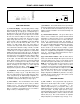
FRONT & REAR PANEL FEATURES
ADVANTAGE SPM522D
Stereo Preamp Mixer
Error IR on
Setup
max
main
zone
min
mute
micchannelpreset
ABC
D
EFG
H
1234
512
zone
main
(1) (2)(3)(4) (5) (6) (7)
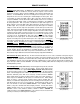
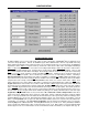
FRONT PANEL FEATURES
(1) Front Panel Display:
This LED display indicates settings
which affect the Main and Zone outputs. Settings are changed via
Remote Controls (pg. 4), Setup (pg. 6), or Configuration (pg. 7).
The Main Preset (A~D) and Zone Preset (E~H) LEDs indicate
which preset is currently active for each output. A preset contains
all of the source and level settings for an output, which are stored
in non-volatile memory for future recall. Presets can be used to
simply change inputs and levels, or to completely re-configure
system operation. When the SPM522D is in 'Room-Combining
Mode', only one Preset LED will be lit (Main or Zone). The
Channel (1~5) LEDs indicate which stereo input channel is
selected for each output. Each channel selection may include its
own customized tone and balance settings. The Mic (1 & 2) LEDs
indicate which mic/line inputs are assigned to each output. When
a mic/line input is set for 'gated' operation, the associated LEDs
will light only when the input is active (gate open). The Main and
Zone (min~max) LED ladders indicate the relative level setting for
each output. These are not signal level meters. Only one LED in
each ladder will be on, indicating the overall level ('fader') setting
for that output. The Mute LEDs indicate when either output is
muted. When an output is muted, the associated level LED will
also remain on. Decreasing the level setting of a muted output
only reduces the level that output will return to when it is un-muted.
However, increasing the level setting of a muted output will
automatically un-mute that output. Similar external Remote
Display Panels are optional (see Remote Controls on pg. 5).
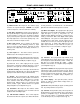
(2) Setup Button:
This momentary push-button is used to enter
Setup Mode (see Setup on pg. 6). Setup Mode allows preset
mixes to be defined and stored in non-volatile memory for future
recall. Setup Mode may be disabled during Configuration (see
Configuration on pg. 11). The Setup button is also used to return
the SPM522D to factory default settings (see Setup on pg. 6).
(3) Error Indicator:
This red LED indicates when unusable
information has been received via remote control (see Remote
Controls on pg. 4). If an error in transmission/reception of a
command occurs, the Error LED will flash. The Error LED will also
flash if a command is received that has been user defined as
having ‘no action’ (see Configuration on pg. 9).
(4) IR Indicator:
This red LED indicates when any information
has been received via remote control (see Remote Controls on pg.
4). If the IR and Error LEDs flash simultaneously, this may be an
indication of improper installation. Check location and wiring of all
infrared receivers.
(5) Internal Infrared Receiver:
This green infrared photo
detector receives commands from optional hand-held Infrared
Transmitters (see Remote Controls on pg. 4). A transmitter will
operate up to 30 feet from the receiver. For best results, there
should be an unobstructed line-of-sight from transmitter to
receiver. When infrared commands are received, the IR LED will
flash. If the IR and Error LEDs flash simultaneously, this may be
an indication of improper installation. The Internal Infrared
Receiver should not be located in direct sunlight, or pointed
directly at fluorescent lighting. Internal Infrared Receiver control
functions are assignable during Configuration (see Configuration
on pg. 10). If desired, the Internal Infrared Receiver may be
manually bypassed (see Options on pg. 6).
(6)(7) Power Switch & Indicator:
When the Power switch is
turned on, the Power LED will light. When power is turned off, all
'current mix' settings (presets, sources, & levels) will be stored in
non-volatile memory and recalled when power is turned back on.
NOTE: The 'current mix' settings are stored only after 5 seconds
of inactivity. If an adjustment to a setting is made less than 5
seconds before power is turned off, the last adjustments that were
followed by a 5 second pause will be the settings stored for recall.
Any adjustments made, without a full 5 second pause before
power off, will be lost (not stored in non-volatile memory).
During Configuration the SPM522D may instead be set to always
recall Main Preset A and Zone Preset E when power is turned
back on (see Configuration on pg. 11).
REAR PANEL FEATURES
(1) Mic 1 & Mic 2:
These plug-in barrier strips provide the
balanced mono mic/line inputs for Mic 1 & Mic 2. For balanced
input, wire high to (+), low to (-), and ground to (
ý
). For
unbalanced input, wire high to (+), and ground to both (-) & (
ý
).
Additional terminals are provided for 'page-over' ducking of the
stereo input signals. By wiring (signal present) to (mute),
automatic ducking will occur whenever signal is present at the Mic
Input. Manual ducking utilizes a switch or contact-closure wired
between (mute) & (
ý
). Mic 1 & Mic 2 functions are assignable
during Configuration (see Configuration on pg. 7 and pgs. 11~13).