
Specifications


3
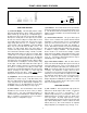
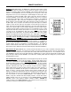
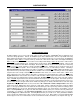
FRONT & REAR PANEL FEATURES
(12) (11) (10) (7) (5) (4) (3) (2) (1)
R
L
R
L
DC
out
30dB
trim
mic 1
patch
30dB
0dB
pad
mic 2
patch
0dB
trim
pad
R
L
mic 2
231
phtm
power
on
mic 1
phtm
power
level
-20dB 0dB
4
5
4
RLRL
-20dB 0dB
-20dB 0dB-20dB 0dB
level
-20dB 0dB
5
sensitivity
010
override
inputs
mono
stereo
zone main
main
limit
zone
limit
zone out main out
outputs
27V ~
15 Watts
MADE IN U.S.A.
BIAMP SYSTEMS
Portland, Oregon
an affiliate of
Rauland-Borg Corp.
translator
override
1
level
2
level
3
level
limit limit
serial port
on
remote
override
+10
+10
remote display
high
low
gnd
IR3
IR2
gnd
1
IR3
IR2
gnd
2
mute
signal present
mute
signal present
sig pres
gnd
override
50/60 Hz
class 2 wiring
chassis gnd
(17) (16) (15) (14) (13) (9) (8) (6)
(2) Phantom Power:
When depressed, these switches supply
+24 Volts to the respective Mic Inputs.
CAUTION: Use only with
condenser microphones. Turn levels down before switching.
(3) Trim, Pad, & +10 Indicator:
The Trim controls adjust gain at
the respective Mic Inputs to compensate for different signal levels.
For best performance, set Trim so the +10 Indicator is activated
only by occasional peaks in signal level. Depress the Pad switch
when input signal levels exceed normal operating range of the
Trim control, or when line-level input is desired.
(4) Mic 1 & Mic 2 Patch:
These 3-conductor 1/4" phone jacks
are for connection of other Advantage products (or signal
processors) to the respective Mic Inputs. Patch jacks are wired
with Tip as send (output), Ring as return (input), and Sleeve as a
common ground.
(5) Stereo Inputs 1~3:
These RCA connectors provide the
unbalanced stereo line-level inputs for Channels 1~3.
(6) Stereo Inputs 4 & 5:
This plug-in barrier strip provides the
unbalanced stereo line-level inputs for Channels 4 & 5. Channel 5
includes an optional internal 30dB pad (see Options on pg. 6).
(7) Level 1~5:
These controls adjust gain at the respective
Stereo Inputs to compensate for different signal levels. For best
performance, reduce gain only on channels having higher levels.
(8) Override Sensitivity:
This control adjusts the threshold level
at which Channel 5 Override will occur, when being triggered by
signal present at the Channel 5 Input (see Override below).
(9) Override:
These plug-in barrier strip terminals provide
Channel 5 Override, which is a priority selection of the Channel 5
input over all other stereo inputs. Wiring (sig pres) to (override)
causes automatic override whenever signal is present at the
Channel 5 Input. Manual override uses a contact-closure wired
between (override) & (gnd). Override functions are assignable
during Configuration (see Configuration on pg. 14).
(10) Stereo/Mono:
When depressed, these switches combine
the respective stereo signals into a mono sum, which is then fed
equally to both the Left & Right outputs.
(11) Limit Threshold & Indicator:
These controls adjust the
threshold level at which the respective stereo limiters will activate.
For best performance, set Limit Threshold so the Limit Indicator
lights when the maximum desired output level is reached.
(12) Main & Zone Outputs:
These plug-in barrier strips provide
the balanced stereo line-level Main & Zone Outputs. For balanced
output, wire high to (+), low to (-), and ground to (
ý
). For
unbalanced output (-6dB gain), wire high to (+) and ground to (
ý
),
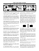
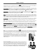
leaving (-) unconnected. Main & Zone Outputs include optional
internal 20dB pads. These pads are useful in applications where
the amplifiers have no level controls. Two pair of jumpers (J6 & J7
for Main; J4 & J5 for Zone) are located on the right edge of the
upper circuit board. To activate either 20dB pad, move both
jumper straps backward one pin, toward the rear panel (see
diagrams below). For access instructions, see Options on pg. 6.
0dB
-20dB
J4
J5
ZONE
0dB
-20dB
J6
J7
MAIN
(13) Translator:
These plug-in barrier strip terminals accept
certain third-party remote controls, which use the 'serial' protocol.
The Low input is for controls with low idle (-15VDC ~ +2VDC). The
High input is for controls with high idle (+2VDC ~ +15VDC).
Translator control functions are assignable during Configuration
(see Configuration on pg. 10).
(14) Remote 1 & Remote 2:
This plug-in barrier strip accepts two
optional remote controls (see Remote Controls on pg. 4). Remote
controls may be infrared, wall-mount, and/or customized, and may
be wired up to 2000 feet away from the unit. Remote 1 & Remote
2 control functions are assignable during Configuration (see
Configuration on pg. 10).
(15) Remote Display:
This 5-pin DIN (female) connector
provides an output for optional Remote Display Panels (see
Remote Controls on pg. 5).
(16) DC Out:
This 6-pin Modular jack supplies ±12 VDC @ 10mA
max., for powering external accessory devices.
(17) Serial Port:
This 9-pin Sub D (male) connector provides an
RS-232 Serial Port. PC Control Software and a serial cable are
provided (see Configuration on pg. 7). The Serial Port also allows
remote control via computer, or via third-party controllers which
use the 'RS-232' protocol (see Computer Control on pg. 15).