
Specifications


5
REMOTE CONTROLS
Wall-Mount
(Biamp #909-0074-00)
:
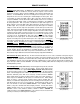
The Wall-Mount is a "hard-wired" control, which is powered
by the SPM522D. There are no batteries to wear out, and it is not easily lost or stolen. The wall-
mount may be wired up to 2000 feet from the SPM522D, using 2-conductor shielded cable (not
included). To install Wall-Mount, first remove mounting box from front panel. Route cable
through "knock-out" hole on rear of mounting box. Install mounting box in wall or panel. Three
screw terminals on circuit board ("GND", "IR2", & "IR3") correspond to "Remote" terminals on
rear panel of SPM522D. Connect cable shield to "GND" terminals at each end. Use conductors
to connect "IR2" to "IR2" & "IR3" to "IR3". Install front panel on mounting box. The Wall-Mount
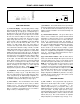
has twenty-eight buttons. Main (1~5) buttons select which stereo input channel (plus tone &
balance settings) is routed to the Main output. Main (A~D) buttons select the desired preset for
the Main output. Zone (1~5) buttons select which stereo input channel (plus tone & balance
settings) is routed to the Zone output. Zone (E~H) buttons select the desired preset for the Zone
output. From the factory, button D/5 (Main) and H/5 (Zone) select stereo input channel #5 to be
routed to the respective outputs. However, during Configuration each of these buttons may be
re-defined to instead recall the respective presets D & H (see Configuration on pg. 9). During
Setup Mode the Main (A~D) and Zone (E~H) buttons are used to store the respective presets
(see Setup on pg. 6). The MUTE buttons (Mic 1, Mic 2, Zone, & Main) turn off the respective
mic/line input or stereo output signals. The Vol
▲
& Vol
▼
buttons (Mic 1, Mic 2, Zone, & Main)
adjust the level setting of the respective mic/line input or stereo output signals. Decreasing the
level setting of a muted input/output only reduces the level that input/output will return to when it
is un-muted. However, increasing the level setting of a muted input/output automatically un-
mutes that input/output. When a mic/line input is set for 'gated' operation, level settings can be
adjusted only when the input is active (gate open). The way in which an SPM522D responds to
remote control buttons may be completely re-defined during Configuration (see Configuration on
pg. 9) The green LED will light when the Wall-Mount receives power from the SPM522D. The
red LED will flash whenever the Wall-Mount is transmitting information. The Wall-Mount
includes an infrared detector, which allows it to operate as an Infrared Receiver, as well. The
infrared detector may be disabled via an internal circuit board jumper strap (labelled "IR RECV").
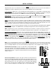
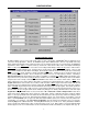
Wall-Mount Panel
(Biamp #909-0074-00)
MAIN
MIC 1 MIC 2 ZONE MAIN
ZONE
A
1234
B C D 5
MUTE
VOL
VOL
MUTE
VOL
VOL
MUTE
VOL
VOL
MUTE
VOL
VOL
1234
E F G H 5
preset
preset
SPM 522D
Remote Interface Kit
(Biamp #909-0041-00)
:
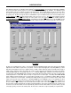
The Remote Interface Kit allows the user to create a customized control panel, using his
own switches, enclosure, and panel. It can provide up to 40 buttons (12 more than standard remote controls), which are supported by the
SPM522D. The Remote Interface Kit is a tested circuit board assembly, which includes two wiring harnesses. The circuit board connects
to the SPM522D in exactly the same way the Infrared Receiver or Wall-Mount does, using 2-conductor shielded cable (not included), and
may be wired up to 2000 feet from the SPM522D. The circuit board is 2.27"W by 2.65"H, with four mounting holes (2" centers) and #6
mounting hardware provided.
Remote Display Panels
(Biamp #909-0082-00)
:
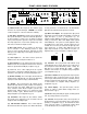
Remote Display Panels provide the same LED
indicators as those found on the Front Panel Display. Remote Display Panels may be
connected to an SPM522D via a separate
Remote Display Controller
(Biamp #909-0080-00).
The Remote Display Controller provides power and connection for up to two Remote Display
Panels. Remote Display Panels are similar to the Wall-Mount remote control in that they are
hard-wired, wall-mount panels, which can be located up to 2000 feet from the SPM522D.
Remote Display Panels also include an infrared detector, which can be wired separately to a
Remote input on the SPM522D, and will operate as an Infrared Receiver. Remote Display
Panels are wired to a Remote Display Controller using 4-conductor shielded cable (not
included). To install Remote Display Panels, first remove mounting box from front panel. Route
cable through "knock-out" hole on rear of mounting box. Install mounting box in wall or panel.
Five screw terminals on circuit board ("POWER GROUND", "+10v", "SHIELD", "DATA+", &
"DATA-") correspond to terminals inside Remote Display Controller. Connect cable shield to
"SHIELD" terminals at each end. Use conductors to connect "POWER GROUND" to "POWER
GROUND", "+10V" to "+10V", "DATA+" to "DATA+", & "DATA-" to "DATA-".
CAUTION: Th
e
combined resistance of the 'POWER GROUND' & '+10V' conductors must not exceed 32 ohm
s
(16 ohms per conductor).
Install front panel on mounting box.
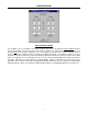
12345 1 2
main
zone
micchannel
ABCD
EFGH
main
preset
zone
12345 1 2
zone main
mute
min
max
IR receiver
SPM522D Remote Display Panel
Remote Display Panel
(Biamp #909-0082-00)