
Specifications


6
SETUP / OPTIONS
SETUP
Setup Mode allows presets to be defined and stored in non-volatile memory, without the need to use the PC Control Software for
Configuration via computer. Setup Mode may also be used to return the SPM522D to the factory default settings.
To enter Setup Mode: While power is on, press and hold the front panel Setup button for 5 seconds (until the currently lit Front Panel
Display LEDs begin flashing). The Front Panel Display LEDs are the only indication that the SPM522D is in Setup Mode, and they will
continue flashing as long as Setup Mode is active.
NOTE: Remote Display Panel LEDs will not flash during Setup Mode.
During Setup Mode: The Remote Control buttons which were assigned to recall presets are temporarily re-defined to store those presets.
All other Remote Control buttons will function normally. This allows a preset to be created by first adjusting the various source and level
settings for the respective output, then pressing the appropriate 'store' button.
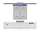
Example: From the factory, six buttons are assigned to recall presets (Main Preset A~C and Zone Preset E~G). During Setup Mode,
these six buttons would become their own respective store buttons. Once the desired stereo input channel, mic/line input levels, and Main
output level settings were made, pressing the Main Preset A button would store those settings. After exiting Setup Mode, those same
settings could easily be recalled from the non-volatile memory by simply pressing the Main Preset A button.
To exit Setup Mode: Press the front panel Setup button momentarily. The Front Panel Display LEDs will quit flashing and the SPM522D
will immediately exit Setup Mode. The SPM522D will also
automatically
exit Setup Mode after 1 minute of inactivity (no button entries).
NOTE: Configuration may be used to assign the Main Preset D and Zone Preset H buttons to recall presets (instead of selecting stereo
input channel #5). Configuration may also be used to disable the Setup Mode functions described above. See Configuration on pg. 7.
To return to factory default settings: While power is off, press and hold the front panel Setup button. While holding the Setup button, turn
power on. Continue holding the Setup button for 2 seconds (until the Error LED flashes once). The SPM522D will begin setting all 'button
definitions' to their factory defaults (see Configuration on pg. 9). If the Setup button is held another 7 seconds (until the Error LED flashes
twice), the SPM522D will begin setting all "preset mixes' to their factory defaults (see Configuration on pg. 7). If the Setup button is held
another 2 seconds (until the Error LED flashes three times), the SPM522D will begin setting all 'Configuration Options' to their factory
defaults (see Configuration on pgs. 11~14). Whenever the Setup button is released the SPM522D will return to normal operation. The
Setup button may be released at any time, depending upon which factory defaults are desired.
OPTIONS
NOTE:
To access internal modifications, first disconnect power to the unit. Then lay the unit on a flat surface with the front panel facing
forward and the top panel facing up. Remove the top panel (eight screws along the sides and rear; one screw centered behind the front
panel). The following modifications occur on the lower circuit board (see diagrams below). These modifications require no soldering.
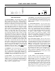
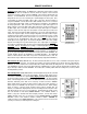
Internal Infrared Receiver Bypass:
A bank of four DIP switches is located toward the right-
center of the circuit board. The far right switch ('IR RECV') is used to activate or bypass the
Internal Infrared Receiver. From the factory, the Internal Infrared Receiver is activated, with the
switch toward the front panel. To bypass the Internal Infrared Receiver, push the switch back,
toward the rear panel.
IR RECV
OPT.W
OPT.X
OPT.Y
X1
C66 C68
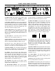
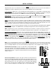
Channel 5 Internal 30dB Pad:
Two jumper straps ('P501' & 'P502') are located toward the rear-
center of the circuit board (underneath the upper circuit board). These jumper straps are used to
activate or bypass a 30dB pad at the Channel 5 input. The 30dB pad allows Channel 5 to accept
greater input signal levels, such as those produced by a 70.7V 'constant voltage' distributed
speaker system. From the factory, the 30dB pad is bypassed, with both jumper straps toward
the left. To activate the 30dB pad, move both jumper straps over one pin, toward the right.
VR401 VR501
C402
C401
C506
C505
P502P501