PMX84 Programmable Matrix Switcher Operation Manual ® Biamp Systems, 10074 S.W. Arctic Drive, Beaverton, Oregon 97005 U.S.A. (503) 641-7287 http://www.biamp.com an affiliate of Rauland-Borg Corp.
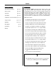
PMX84 TABLE OF CONTENTS INTRODUCTION Front & Rear Panel Features pgs. 2 & 3 Remote Controls pgs. 4 & 5 Logic Inputs pgs. 6 & 7 Logic Outputs pgs. 8 & 9 Configuration - PC Control Software pgs. 10~12 Computer Control pgs. 13~15 Applications pgs.
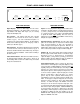
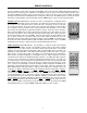
FRONT & REAR PANEL FEATURES 1 output A output B output C output D input channels 2 3 4 5 6 7 input channels 2 3 4 5 6 7 input channels 2 3 4 5 6 7 input channels 2 3 4 5 6 7 8 1 8 1 8 1 ADVANTAGE PMX84 Programmable Matrix Switcher 8 error remote power o FRONT PANEL FEATURES REAR PANEL FEATURES Output Displays: These four LED displays show the various input/output assignments of the matrix switcher.
FRONT & REAR PANEL FEATURES remote inputs 1 2 3 inputs outputs BIAMP SYSTEMS Portland, Oregon 4 B an affiliate of Rauland-Borg Corp. MADE IN U.S.A.
REMOTE CONTROLS The type and quantity of remote controls are optional for the PMX84. Remote controls affect the individual input/output assignments, as well as selection of more global ‘preset’ assignments (see Configuration on pg. 10). Remote controls may be added at any time, and do not require the PMX84 to be modified, opened, or removed from a rack. There are four types of remote controls available: The Infrared Transmitter, the Infrared Receiver, the Wall-Mount Panel, and the Remote Interface Kit.
REMOTE CONTROLS Wall-Mount (Biamp #909-0075-00): The Wall-Mount is a "hard-wired" control, which is powered by the PMX84. There are no batteries to wear out, and it is not easily lost or stolen. The WallMount may be wired up to 2000 feet from the PMX84, using 2-conductor shielded cable (not included). To install the Wall-Mount, first remove the mounting box from the front panel. Route the cable through a "knock-out" hole on the rear of the mounting box. Install the mounting box in a wall or panel.
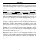
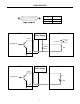
LOGIC INPUTS The sixteen Logic Inputs are available on a rear panel 25-pin Subminiature D (female) connector. Logic Inputs allow remote control of PMX84 input/output assignment & Logic Output functions via external circuits, such as switches, contact-closures, active driver circuits, and/or ‘open-collector’ logic outputs. From the factory, all Logic Inputs are non-functional and may be programmed to perform functions only through Configuration (see Configuration on pg. 10).
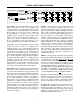
LOGIC INPUTS 13 1 25 14 logic inputs logic inputs pin numbers logic #1~16 pin #1~16 ground pin #17~25 multiple switches to single Logic Input 13 25 1 14 single switch to multiple Logic Inputs 13 25 1 14 multiple switches to multiple Logic Inputs (diode isolation) 13 25 1 14 7
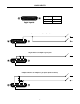
LOGIC OUTPUTS The sixteen Logic Outputs are available on a rear panel 25-pin Subminiature D (male) connector. Logic Outputs provide remote control of external circuits, such as relays and/or indicators. From the factory, all Logic Outputs are ‘off’ and access to them is available only through Configuration (see Configuration on pg. 10).
LOGIC OUTPUTS 1 13 14 25 logic outputs pin numbers logic #1~16 pin #1~16 ground pin #17~25 logic outputs PMX84 Pin #1 +12 Volts DC Power Supply − + 12V Relay Contacts normally closed common normally open Logic Output #1 1N4004 Diode Coil Pin #25 PMX84 Pin #1 +12 Volts DC Power Supply − + Indicator Panel R Logic Output #1 LED Pin #25 9
CONFIGURATION ® All Configuration parameters are adjustable using the Windows 95 'PC Control Software' and serial cable provided with the PMX84. The ® PC Control Software provides programs for various ADVANTAGE products, including the PMX84. The PMX84 program includes multiple control screens, which are described on the following pages. Factory default settings are shown on each screen.
CONFIGURATION BUTTON DEFINITION SCREENS Button Definition screens are used to assign specific ‘actions’ to remote control buttons (and logic inputs). Button Definition screens are accessed through the Configure PMX84 drop-down menu. There are five Button Definition screen tabs to choose from (Remote 1~4 & Logic Inputs). Button Definition screens are divided into two sections. The right section indicates which Remote Control Button is currently selected.
CONFIGURATION CONFIGURATION OPTIONS SCREEN The Configuration Options screen has three sections. The top section displays the Serial Number & Firmware Version for the current PMX84 (if operating ‘on-line’). The PC Control Software can operate ‘off-line’ (with no product connected) by opening a ‘new’ file for the desired product. The Serial Number & Firmware Version are not displayed for ‘new’ (off-line) files.
COMPUTER CONTROL ® The ADVANTAGE PMX84 has an RS-232 compatible serial interface, which allows it to be controlled by a computer (see Rear Panel Features on page 3). In addition to the PC Control Software, the PMX84 offers two other methods of computer control. Control Button Emulation: This method allows the computer to emulate the operation of the infrared transmitter or wall-mount control panel.
COMPUTER CONTROL Serial Interface Electrical Connections & Cabling: The 9-pin Subminiature D (male) connector on the PMX84 rear panel provides the RS-232 compatible serial interface signals used for computer control. The PMX84 transmits serial data on pin 3 (TxD) and receives serial data on pin 2 (RxD). The serial interface ground is on Pin 5. The DTR & RTS signals are connected to the +12 Volt power supply (each through its own resistor) and are always asserted when the PMX84 power is on.
COMPUTER CONTROL PMX84 to PC 9-Pin Connector 9-pin PMX84 n/a RxD TxD DTR ground n/a RTS n/a n/a male female 1 2 3 4 5 6 7 8 9 1 2 3 4 5 6 7 8 9 n/a RxD TxD DTR ground n/a RTS n/a n/a male female 1 2 3 4 5 6 7 8 9 1 2 3 4 5 6 7 8 9 n/a RxD TxD DTR ground n/a RTS n/a n/a male 1 2 3 4 5 6 7 8 9 1 2 3 4 5 6 7 8 9 9-pin n/a RxD TxD DTR ground n/a RTS n/a n/a #3 male 1 2 3 4 5 6 7 8 9 These connections may not be required: DTR to CD; DTR to DSR; or RTS to CTS.
APPLICATIONS Zone Paging with Background Music Programming of the PMX84 for this application can be done simply by opening & downloading a file (page1a.pmx) during Configuration. This application shows (1) master & (4) zone paging microphones connected to an Advantage EX module. The EX module provides the mic preamplification necessary before entering the PMX84 (line-level signals do not require preamplification).
APPLICATIONS Zone Paging with Background Music & Emergency Override Programming of the PMX84 for this application can be done by simply opening & downloading a file (page1b.pmx) during Configuration. This application is identical to the application on the previous page, except that an emergency override signal has been added.
APPLICATIONS ‘In-Line’ Room Combining Programming of the PMX84 for this application can be done by simply opening & downloading a file (inline4a.pmx) during Configuration. This application shows (4) rooms in a row (‘inline’). Each room has (2) mics & (1) auxiliary input connected to an Advantage 301e. The 301e mic/line mixers provide mixing, remote level control, auto-muting of aux inputs, and balanced line-level outputs for Rooms 1~4.
APPLICATIONS ‘In-Line’ Room Combining with Program Sources & Emergency Paging Programming of the PMX84 for this application can be done by simply opening & downloading a file (inline4b.pmx) during Configuration. This application is identical to the application on the previous page, except that (2) program sources and an emergency paging signal have been added. Program sources 1 & 2 are connected to Inputs 5 & 6 of the PMX84, respectively.
APPLICATIONS ‘Square’ Room Combining Programming of the PMX84 for this application can be done by simply opening & downloading a file (square1a.pmx) during Configuration. This application shows (4) rooms in a ‘square’. Each room has (2) mics & (1) auxiliary input connected to an Advantage 301e. The 301e mic/line mixers provide mixing, remote level control, auto-muting of aux inputs, and balanced line-level outputs for Rooms 1~4.
APPLICATIONS ‘Square’ Room Combining with Program Sources & Emergency Paging Programming of the PMX84 for this application can be done by simply opening & downloading a file (square1b.pmx) during Configuration. This application is identical to the application on the previous page, except that (2) program sources and an emergency paging signal have been added. Program sources 1 & 2 are connected to Inputs 5 & 6 of the PMX84, respectively.
PMX84 Block Diagram patch +10 signal detect Inputs 1~8 Outputs A~D 8-by-4 crosspoint matrix level level 2 22 3 Remote Ports 1~4 4 5 front panel input/output assignment displays (x4) 6 Emergency Override Serial Port Logic Inputs 1~16 microprocessor Logic Outputs 1~16 7 8 PMX Link BLOCK DIAGRAM 1 expansion input
SPECIFICATIONS Frequency Response (20Hz~20kHz @ +4dBu): +0/-0.2dB Total Harmonic Distortion (20Hz~20kHz @ +4dBu): < 0.007% Output Noise (20Hz~20kHz @ unity gain): one input assigned -93dBu eight inputs assigned -87dBu Maximum Gain (input & output level controls max.
WARRANTY BIAMP SYSTEMS IS PLEASED TO EXTEND THE FOLLOWING 5-YEAR LIMITED WARRANTY TO THE ORIGINAL PURCHASER OF THE PROFESSIONAL SOUND EQUIPMENT DESCRIBED IN THIS MANUAL. BIAMP Systems expressly warrants this product to be free from defects in material and workmanship for a period of 5 YEARS from the date of purchase as a new product from an authorized BIAMP Systems dealer under the following conditions. 1.