
Specifications


2
FRONT & REAR PANEL FEATURES
123456 87
input channels
output A
123456 87
input channels
output B
123456 87
input channels
output C
123456 87
input channels
output D
error remote power
Programmable Matrix Switcher
ADVANTAGE PMX84
o
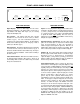
FRONT PANEL FEATURES
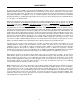
Output Displays: These four LED displays show the various
input/output assignments of the matrix switcher. Each group of
eight indicators will display which Inputs (1~8) are currently
assigned to that Output (A~D).
Error Indicator: This indicator will flash when unusable
information has been received via remote control (see Remote
Controls on pg. 4). If an error in transmission/reception of a
command occurs, the Error indicator will flash. The Error Indicator
will also flash continuously whenever an emergency override is
activated (see Override on pg. 3).
Remote Indicator: This indicator will flash when any information
is received via remote control (see Remote Controls on pg. 4). If
the Remote and Error indicators flash simultaneously, this may be
an indication of improper installation. Check location and wiring of
all remote controls.
Power Switch & Indicator: When the Power Switch is turned on,
the adjacent indicator will light. When power is turned off, all
current settings will be stored in non-volatile memory and recalled
when power is turned back on.
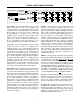
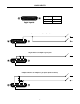
REAR PANEL FEATURES
Inputs 1~8: These plug-in barrier strips provide the balanced line-
level inputs to the matrix switcher. For balanced input, wire high to
(+), low to (-), and ground to (
ý
). For unbalanced input, wire high
to (+) and ground to both (-) & (
ý
). When using multiple PMX84s
to expand the matrix output capability, wire each source (in
parallel) to the respective input on each PMX84. From the factory,
all Inputs are assigned to all Outputs.
Input Trim Controls & +10 Indicators: The Trim controls adjust
gain at the associated inputs to compensate for different signal
levels. For best performance, set Trim so the +10 indicator is
activated only by occasional peaks in signal level. When the +10
indicator lights, 8dB of headroom remains before clipping. When
Trim is centered, input to balanced output level will be unity gain.
Outputs A~D: These plug-in barrier strips provide the balanced
line-level outputs from the matrix switcher. For balanced output,
wire high to (+), low to (-), and ground to (
ý
). For unbalanced
output, wire high to (+) and ground to (
ý
), leaving (-) unconnected.
Signal level will be reduced by 6dB when outputs are unbalanced.
From the factory, all Inputs are assigned to all Outputs.
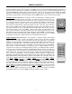
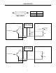
Patch & Expansion Input: These 3-conductor 1/4” phone jacks
allow insertion of external signal processing at the Outputs, as well
as inter-connection of multiple PMX84s to expand the matrix input
capability. Patch jacks are wired with Tip as send, Ring as return,
and Sleeve as a common ground. They may be used to provide
both input and output for external signal processing devices, such
as remote controls & equalizers. Expansion Input jacks are wired
with Tip as input, Ring as output, and Sleeve as a common
ground. They are used in conjunction with the Patch jacks on
other PMX84s, to increase the number of inputs assignable to the
matrix. For this purpose, Expansion Input jacks are connected to
Patch jacks using 3-conductor 1/4” phone cables (Biamp #909-
0013-00). To combine the inputs of two PMX84s, connect the
Patch jacks of the first unit to the Expansion Input jacks of the
second unit. Both units will provide identical matrix output signals,
with all sixteen inputs being assignable. Additional PMX84s may
be connected in this same fashion, to further increase the matrix
input capacity. External signal processing may still be inserted at
the Outputs, by utilizing the Patch jacks available on the ‘last’
PMX84 in the chain. Signal processing inserted here will affect the
Outputs of all PMX84s in the chain.