
Specifications


4
REMOTE CONTROLS
The type and quantity of remote controls are optional for the PMX84. Remote controls affect the individual input/output assignments, as
well as selection of more global ‘preset’ assignments (see Configuration on pg. 10). Remote controls may be added at any time, and do
not require the PMX84 to be modified, opened, or removed from a rack. There are four types of remote controls available: The Infrared
Transmitter, the Infrared Receiver, the Wall-Mount Panel, and the Remote Interface Kit. The PMX84 may also be controlled via switches
(Logic Inputs), computer (RS-232), and various third-party controllers. NOTE: Remote controls come with complete instructions.
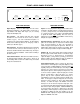
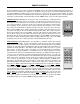
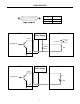
Infrared Receiver (Biamp #909-0030-00): The Receiver consists of a black plastic box, containing an infrared
photo detector, an LED indicator, and five screw terminals. To install the Receiver, first take off the front cover
by removing four screws. Mount the Receiver to a wall or other surface, using the two screw holes on the back
cover (screws not included). The Receiver should not be mounted in direct sunlight, or pointed directly at
fluorescent lighting. Receiver performance may be adversely affected by electronic ballasts. For best results,
there should be an unobstructed line-of-sight from Transmitter to Receiver. The Receiver may be wired up to
2000 feet from the PMX84, using 2-conductor shielded cable (not included). Route cable through access hole
on the bottom of the Receiver. Three screw terminals inside the Receiver ("GND", "IR2", & "IR3") correspond to
"Remote Input" terminals on the rear of the PMX84. Connect the cable shield to the "GND" terminals at each
end. Use the two conductors to connect "IR2" to "IR2" & "IR3" to "IR3". Replace the Receiver front cover. The
LED indicator inside the Receiver lights when infrared information is detected. NOTE: The Infrared Receiver
also includes two 'Remote Translator' terminals ("GND" & "XLATE"), which allow remote control of the PMX84
via third-party 'serial' controllers. Complete instructions are included with the Infrared Receiver.
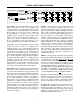
InfraRed Transmitter (Biamp #909-0065-00): The Transmitter is a hand-held controller, which transmits
infrared codes unique to Biamp. Therefore, the Transmitter should not affect any other infrared controlled
equipment (such as TVs or VCRs). Likewise, other infrared controllers will not provide proper control of Biamp
equipment. The Transmitter requires two AAA batteries, which are included with the unit (user installed). The
Transmitter has twenty-eight buttons. Each button is labelled with both a number and a letter, as a generic
button reference. From the factory, remote control buttons are non-functional and may be programmed to
perform functions only through Configuration (see Configuration on pg. 10). During Configuration, each remote
control button may be defined as an individual input/output assignment, or as multiple input/output assignments
(such as a preset). Control buttons are defined to affect input/output assignments using ‘on’, ‘off’, ‘toggle’, and
‘no operation’ functions. Each control button can have different functions assigned to it, depending upon which
Remote Input (1~4) it is received from. This is an effective way to customize remote control functions for specific
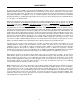
zones or locations. By downloading a specific file (‘startup.pmx’) during Configuration, the PMX84 may be
programmed so that each button assigns a specific input to a specific output. Under these circumstances, the
button labelling indicates which input (number) is assigned to which output (letter). (Example: button ‘1 A’
assigns Input 1 to Output A
; button ‘2 B’ assigns Input 2 to Output B; button ‘3 C’ assigns Input 3 to Output C;
button ‘4 D’ assigns Input 4 to Output D; etc.). This file does not allow Input 8 to be assigned via the Transmitter.
It is reserved as an ‘emergency/all-call’ input, which can be assigned to Outputs A~D using the Override terminal
(see Rear Panel Features on pg. 3). This file also designates a ‘toggle’ function for the remote control buttons.
This ‘toggle’ function works as a ‘push-on/push-off’ assignment. (Example: pressing button ‘7 A’ once assigns
Input 7 to Output A
; pressing button ‘7 A’ again un-assigns Input 7 from Output A; etc.). For best results, there
should be an unobstructed line-of-sight from Transmitter to receiver. The Transmitter will operate up to 30 feet
from a receiver. In addition to the Infrared Receiver described above, receivers are also included on the PMX84
and the Wall-Mount panel (see next page). NOTE: Default button definitions are all ‘no operation’.
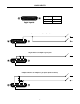
InfraRed Receiver
External Receiver
(Biamp #909-0030-00)
2 A
4 A
3 A
1 A 1 B 1 C 1 D
2 B
4 B
3 B
2 C
4 C
3 C
2 D
4 D
3 D
5 A
7 A
6 A
5 B
7 B
6 B
5 C
7 C
6 C
5 D
7 D
6 D
ADVANTAGE PMX84
Infrared Transmitter
(Biamp #909-0065-00)