
Specifications


8
LOGIC OUTPUTS
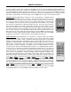
The sixteen Logic Outputs are available on a rear panel 25-pin Subminiature D (male) connector. Logic Outputs provide remote control of
external circuits, such as relays and/or indicators. From the factory, all Logic Outputs are ‘off’ and access to them is available only through
Configuration (see Configuration on pg. 10). During Configuration, remote control buttons and Logic Inputs may be defined to control
switching of the various Logic Outputs, utilizing ‘on’, ‘off’, ‘toggle’, and/or ‘no operation’ commands.
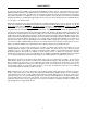
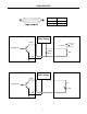
The PMX84 logic outputs are ‘open collector’ outputs. Each logic output is an NPN transistor with the collector being the output and the
emitter being ground (see diagram on next page). When a logic output is turned on, the transistor provides a path for DC current to flow.
The logic outputs do not provide any voltage or current. They act only as switches (with a common ground return). To activate external
relays, an external power supply must be used (see diagram on next page). The logic output transistors are rated up to a maximum of 24
VDC and 50 mA per output (24 volt relay coils maximum). However, +12 Volts DC is sufficient power for most applications. When using
the logic outputs to control relays, protection diodes must be used to suppress high voltage transients that are generated when the relays
turn off (see diagram below). Any of the 1N4004 family of diodes (1N4001, 1N4002, 1N4003, 1N4004, 1N4005, 1N4006, 1N4007, or
equivalent) will provide proper protection. A 12 Volt Power Supply (#929-0011-00), 12 Volt DPDT Relays (#520-0064-00), and 1N4004
Diodes (#190-0003-09) are available from Biamp. When a logic output goes on, the associated relay may be wired to perform on, off, or
‘A/B’ switching functions. To use a logic ‘on’ command to turn on (or activate) a device, wire across the ‘normally open’ relay contacts, in
series with the device (or control voltage source). To use a logic ‘on’ command to turn off a device (or speaker), wire across the ‘normally
closed’ relay contacts, in series with the device (or control voltage source). To use a logic ‘on’ command to select between ‘A’ or ‘B’
signals (inputs or outputs), wire one to the ‘normally closed’ relay terminal and the other to the ‘normally open’ relay terminal, with the
common relay terminal providing the feed (input or output).
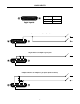
Likewise, Logic Outputs may be used in conjunction with an external power supply, for controlling external indicators such as LEDs (see
diagram on next page). When a Logic Output goes on, the circuit for the external indicator is completed (Logic Output provides path for
DC current to flow). Again, a +12 Volts DC power supply is appropriate. Typically, an LED will require about 8 mA of current to achieve
sufficient brightness. Therefore, the value of ‘R’ should be 1.2k ohms. If the LED used requires more current to achieve sufficient
brightness, the value of ‘R’ may be reduced to a minimum of 1k ohm. This would provide 10 mA of current to the LED. Remote control
buttons and Logic Inputs can be defined to control matrix input/output assignments and/or Logic Output switching. Therefore, external LED
circuits may be used to indicate virtually anything, including PMX84 matrix input/output assignments or status of external systems.