
User guide


8
4th Floor
3rd Floor
2nd Floor
1st Floor
Zone 5
speakers
Zone 4
speakers
Zone 3
speakers
Zone 2
speakers
Zone 1
speakers
Zone 6
speakers
Zone 7
speakers
Zone 8
speakers
Zone 5
speakers
Zone 4
speakers
Zone 3
speakers
Zone 2
speakers
Zone 1
speakers
Zone 6
speakers
Zone 7
speakers
Zone 8
speakers
Zone 5
speakers
Zone 4
speakers
Zone 3
speakers
Zone 2
speakers
Zone 1
speakers
Zone 6
speakers
Zone 7
speakers
Zone 8
speakers
Zone 5
speakers
Zone 4
speakers
Zone 3
speakers
Zone 2
speakers
Zone 1
speakers
Zone 6
speakers
Zone 7
speakers
Zone 8
speakers
central
paging
microphone
Channel 5
background music service
Channel 3
background music service
1st Floor
telephone page
2nd Floor
telephone page
3rd Floor
telephone page
4th Floor
telephone page
digital message repeater
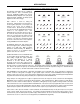
APPLICATIONS
Hospital with Multiple Zones of Paging, Messaging, and Background Music
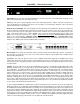
This application demonstrates the use of AUDIA in a
multi-zone hospital building. This is a networked
system using one AudiaFLEX 8x8CM unit and three
AudiaEXPO 8-Output Expander units (eight inputs,
thirty-two outputs, CobraNet). An example system
diagram is shown on the back page.
All inputs (paging microphone, message repeater,
background music, and telephone system) reside on
the first floor of the building, and are connected to
the AudiaFLEX unit located there. The AudiaFLEX
unit also provides the outputs necessary to feed the
eight zones on the first floor. An AudiaEXPO unit is
located on each of the other floors, and provides the
corresponding zone outputs for that floor.
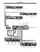
The AudiaFLEX unit distributes the appropriate
signals to the AudiaEXPO units on the other floors
as digital audio via CobraNet. This is beneficial
because some of the input sources are 'unbalanced'
and, as such, should not be routed over long
distances. Additionally, CobraNet affords the
necessary isolation to help avoid ground loops
between the active components located on different
floors. CobraNet also saves on the labor and
expense of wiring, by transmitting all eight of the
associated zone output signals to a given floor over a
single CAT5 cable.
The zone outputs on each of the floors are
connected to an MCA8050 multi-channel amplifier,
located in the same equipment rack as the
AudiaFLEX or AudiaEXPO unit. Each MCA8050
amplifier has eight channels, delivering 50 watts of
power per channel. With eight TDT50 transformers
installed internally, each MCA8050 is prepared to
drive the eight 70 volt distibuted speaker systems on that floor.
CobraNet from the AudiaFLEX unit to the AudiaEXPO units is tied together through an Ethernet switch. This allows sharing of digital audio
signals (CobraNet) on a network. The maximum distance between any AUDIA unit and an Ethernet switch is 300 feet. Therefore, this
system can span up to 600 feet between the first floor equipment rack and any of the other floors. Additional Ethernet switches, or even
fiber-optics, can be used to further extend distances between units on the network.
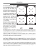
All mixing and processing of signals is accomplished within the AudiaFLEX unit on the first floor. In the system design, the paging
microphone is fed to a Router (1x32) for assignment to the individual zones. The message repeater is fed to a Router (1x4) for assignment
to the four floors. The two background music inputs are both fed to four separate Routers (2x1) for source selection on each of the four
floors. Telephone paging is fed to a set of four Duckers (one for each floor) to provide page-override of the selected background music on
that floor. Output from the message Router is fed to a second set of four Duckers (one for each floor) to provide message-override of the
telephone and music signals on that floor. Finally, output from the microphone Router is fed to a bank of thirty-two Duckers (one for each
zone) to provide master page-override of all other signals in any selected zones. Levelers are utilized on all paging and message inputs
(to provide consistent volume levels), and equalizers are utilized at all outputs (to compensate for building acoustics and enhance
intelligibility).
Various remote control options are available. Volume 8, Select 8, and Volume/Select 8 rotary encoder panels may be used to provide
volume, source selection, and even page routing functions. Two Logic Box control devices could instead provide forty logic inputs, which
would allow all page/message routing and music source selection to be accomplished using external switches on custom control panels.