Vocia® GPIO-1 Operation Manual January 2013 Biamp Systems, 9300 SW Gemini Drive, Beaverton, Oregon 97008 U.S.A. (503) 641-7287 www.biamp.
IMPORTANT SAFETY INSTRUCTIONS IMPORTANT SAFETY INSTRUCTIONS 1) Read these instructions. 2) Keep these instructions. 3) Heed all warnings. 4) Follow all instructions. 10) Use only with equipment rack, cart, stand or table designed to provide adequate mechanical strength, heat dissipation and securement to the building structure. 6) Clean only with dry cloth. When a cart is used, use caution when moving the cart and product combination to avoid injury from tip-over. 7) Do not block ventilation openings.
TABLE OF CONTENTS VOCIA GENERAL PURPOSE INPUT OUTPUT DEVICE (GPIO-1). . . . . . . . . . . . . . . . . . . . . . . . . . 4 Features. . . . . . . . . . . . . . . . . . . . . . . . . . . . . . . . . . . . . . . . . . . . . . . . . . . . . . . . . . . . . . . . . . . . . . . . . . . . . . . . . . . . . . . . . . . 4 Network . . . . . . . . . . . . . . . . . . . . . . . . .
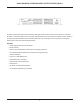
VOCIA GENERAL PURPOSE INPUT OUTPUT DEVICE (GPIO-1) The GPIO-1 provides sixteen general purpose inputs and sixteen general purpose outputs to control various aspects of a Vocia system. The GPIO-1 is a monitored device and can be used in life safety applications where more logic inputs or outputs are required. The GPIO-1 has dual powering from PoE Ethernet ports and alternate powering from dual 24V DC inputs. In the event of power loss changeover between power sources will provide uninterrupted operation.
GPIO-1 SETUP AND USE Setup and Use The Vocia software provides the interface for configuring and programming the GPIO-1. The information supplied by this manual relates to hardware installation, physical connections and device information. For more details on the software setup please consult the Vocia Software Help File. Network The GPIO-1 is designed to be used in a single Vocia World and utilizes the Vocia CobraNet LAN to communicate.
GPIO-1 SETUP AND USE Input Connectors Sixteen parallel input connections are provided on the GPIO-1 as well as Isolated Ground and Ground connections. Under software control the logic level of each input can be set independently to operate one of three ways. • TTL: 2V to 5V logic sense. To enable a TTL input, apply a TTL logic high or low with respect to Isolated Ground. This can be configured in software to detect a low to high or high to low transition.
GPIO-1 SETUP AND USE Output Connectors Sixteen parallel outputs are provided on the GPIO-1 as well as Isolated and Chassis Ground connections. Each output is able to accept either an external positive voltage between 4 and 30V or use the 24V DC 100mA reference voltage provided on the unit. The 24V DC supply for use with the Aux Power port is not provided with the unit and will need to be sourced locally.
GPIO-1 SETUP AND USE Power Caution - Due to potential energy hazard, connections to the Auxiliary Power 24V DC inputs must be made by a qualified electrician or other qualified person as required to conform with all local codes. The GPIO-1 will be capable of operation from two power supply types - PoE and 24V DC. Any or all power sources may be connected concurrently. Loss or return of any power source will not result in interruption to operation.
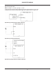
SUGGESTED WIRING Input - High Range Monitored – Active High - 24VDC Locally Sourced Notes: Vocia software configured as High Range Monitored - Active State High. Circuit shown in Low State Input - High Range Monitored – Active High - 24VDC Externally Sourced Notes: Vocia software configured as High Range Monitored - Active State High. Circuit shown in Low State Input - High Range Unmonitored – Active High - 24VDC Locally Sourced Notes: Vocia software configured as High Range - Active State High.
SUGGESTED WIRING Input - 5V TTL Logic Control Notes: Low Voltage = 0 – 0.8 VDC. Logic High = 2 – 5VDC. If configured as Active State High Alarm/Fault/Reset triggers when voltage transitions from Low to High. If configured as Active State Low Alarm/Fault/Rest triggers when voltage transitions from High to Low.
SUGGESTED WIRING Outputs Driving a Relay Powered Externally 11
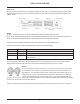
GPIO-1 SPECIFICATIONS Vocia General Purpose Input Output 1 SPECIFICATIONS General Purpose Outputs Quantity 16 Type FET Switch, open drain (low side driver) Max Continuous Current 0.35VA Current Limit 0.8A Maximum External Supply 30V DC VMon Input Shutdown 35V DC General Purpose Inputs Quantity 16 High Range Logic Low 0-8V DC High Range Logic High 12-30V DC TTL Logic Low 0 – 0.
GPIO-1 WARRANTY BIAMP SYSTEMS IS PLEASED TO EXTEND THE FOLLOWING 5-YEAR LIMITED WARRANTY TO THE ORIGINAL PURCHASER OF THE PROFESSIONAL SOUND EQUIPMENT DESCRIBED IN THIS MANUAL 1. BIAMP Systems warrants to the original purchaser of new products that the product will be free from defects in material and workmanship for a period of 5 YEARS from the date of purchase from an authorized BIAMP Systems dealer, subject to the terms and conditions set forth below.
FCC COMPLIANCE FCC NOTICE - CLASS B DIGITAL DEVICE NOTE: This equipment has been tested and found to comply with the limits for a Class B digital device, pursuant to Part 15 of the FCC Rules. These limits are designed to provide reasonable protection against harmful interference in a residential as well as in a commercial environment.
COMPLIANCE DoC VGPIO201205b EC Declaration of Conformity Biamp Systems Corporation, as manufacturer having sole responsibility, hereby declares that our delivered version the following described product complies with the applicable provisions of the DIRECTIVES below except as noted herein. Any alterations to the product not agreed upon and directed by Biamp Systems Corporation will invalidate this declaration.
COMPLIANCE EU RoHS COMPLIANT This Biamp product, including all attendant cables and accessories supplied by Biamp, meets all requirements of EU Directives 2011/65/EU of 8 June 2011, the EU RoHS Recast. An EU RoHS Materials Content Declaration document may be obtained at www.biamp.com The following information is presented to comply with Chinese law SJ/T11363-2006.