
Specifications

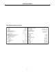


2
FRONT & REAR PANEL FEATURES
on
signal
peak
temp
fault
MXA300
321456
master
bass
0
+
0
+
treble
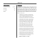
On Indicator: This green LED remains lit when AC power is
applied to the unit.
Signal/Clip Indicator: This 2-color LED indicates the signal
level for the amplifier. When the LED is green, the amplifier has
signal (above -30dB). When the LED is red, the amplifier signal
is clipping (max. power). CAUTION: Signal levels should be
adjusted to avoid clipping. Clipping can cause distortion, over-
temperature conditions, and even loudspeaker damage.
Temp/Fault Indicator (not present on model MXA35): This red
LED indicates over-temperature and output fault conditions for
the amplifier. When the LED remains lit, the amplifier has an
over-temperature condition. When the LED is flashing, the
amplifier has an output fault condition. Either condition will
temporarily de-activate the amplifier, causing the Signal/Peak
LED to turn off as well. The amplifier will attempt to self-reset
once the over-temperature or output fault condition is resolved.
NOTE: Signal/Peak indicators will turn off during Temp/Fault
conditions (see Signal/Peak & Temp/Fault Indicators above).
Level (Channels 1~6): These controls adjust the amount of
signal sent from the individual input channels to the mixer
output. Optimum Level setting is near the 12 o'clock position
(unity gain).
Level (Master): This control adjusts the amount of signal sent
from the mixer output to the amplifier input. The Master Level
control is used to adjust the overall volume of the system.
Bass: This screwdriver control adjusts the low-frequencies
("Bass") at the mixer output (±12dB @ 50Hz).
Treble: This screwdriver control adjusts the high-frequencies
("Treble") at the mixer output (±12dB @ 10kHz).
input
1
input
2
channel 1
min max
peak
channel 2
peak
trim
min max
trim
min max
trim
min max
trim
min max
trim
min max
min
maxmin max
min
max
min max
trim
input
3
channel 3
peak
input
4
channel 4
peak
input
5
channel 5
peak
input
6
channel 6
off
low cut
off
link
link
on
off
on
peak
auto mute
sensitivity
limiter
threshold
70V100V 25V
class 2 wiring
class 3
wiring
com
pre out
+10VC
EQ in
line out amp in
xfmr
input
4Ω gnd
chime
level
CAUTION:
Risk of fire -
replace fuse only
with same type
~
120/240VAC 50-60Hz 300W
FUSE: T 8A/4A L 250V 120V/240V
Music
On
Hold
output
Music On
Hold level
remote
level
control
mute/chime
mic/line
tel
BIAMP SYSTEMS
120V
F
U
S
E
F
U
S
E
O
phantom pwr
priority
auto mute
manual mute
-80dB
on
on
on
on
-20dB
phantom pwr
priority
auto mute
manual mute
-80dB
on
on
on
on
-20dB
phantom pwr
priority
auto mute
manual mute
-80dB
on
on
on
on
-20dB
phantom pwr
priority
auto mute
manual mute
-80dB
on
on
on
on
-20dB
phantom pwr
priority
auto mute
manual mute
-80dB
on
on
on
on
-20dB
phantom pwr
priority
auto mute
manual mute
-80dB
on
on
on
on
-20dB
MXA300
UL 60065
WARNING: RISK OF HAZARDOUS ENERGY.
SEE INSTALLATION MANUAL.
Designed in Oregon, U.S.A.
Assembled in India
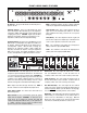
AC Power Entrance: The switch applies power to the unit. The
receptacle accepts the detachable Power Cord. The Power Cord
is for connection to three-prong grounded outlets. CAUTION: Do
not remove or defeat the ground prong on the Power Cord, as this
constitutes a shock hazard. Equipment shall be connected to a
mains socket outlet with a protective earthing connection. Plug is
main disconnecting device and it shall remain readily operable.
Fuse: Replace Fuse with same type and value only. NOTE: If
the Fuse continues to blow, the amplifier may require service.
Power Selector Switch: This switch selects either 120 Volt or
240 Volt AC operation.
Output Connector: These screw terminals provide the speaker
outputs from the amplifier. CAUTION: To reduce the risk of
electric shock, do not perform any servicing other than that
contained in this Operation Manual unless you are qualified to do
so. Output connections must be made by qualified service
personnel only (refer to the Installation Manual).
Chime Level: This control adjusts the volume level of a chime
tone (see Mute/Chime below). To turn the chime tone off
completely, set this control to the counter-clockwise position (min).
Limiter Threshold: This control adjusts the threshold level at
which the internal limiter circuit is activated. To turn the limiter off
completely, set this control to the clockwise position (max).
Auto Mute Sensitivity: This control adjusts the level at which
signals from "priority" channels will automatically trigger muting of
selected non-priority
channels (see DIP Switches on next page).
To increase auto mute sensitivity, turn this control clockwise.
Mute/Chime: This terminal (plus the adjacent
d
terminal) allows
manual muting of selected channels via an external switch or
contact closure (see DIP Switches on next page). When the
Chime Level control is turned up (on), a pre-announcement chime
tone will also be activated by the switch or contact closure.