
Manual


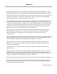


Tesira EX-IN, EX-AEC, EX-OUT & EX-IO – REAR PANEL
!
!
!
%!
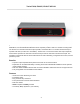
Tesira EX-IN, EX-AEC, EX-OUT & EX-IO Rear Panel
1.
Grounding pin
. This pin is for grounding the chassis of the expander.
2.
AVB / Control Connection
. Supports Standard RJ-45 connector with CAT-5, CAT-5e, CAT-6 or
CAT-7 cabling. The expander must receive PoE+ power (IEEE 802.3at) on this connector in order for
proper operation. The maximum distance between any unit and an Ethernet switch is 328 feet (100
meters).
This connection is for sending and receiving AVB audio signals as well as sending and receiving data
between the expander device and the Tesira system. An expander will not operate if it is not on a
network that includes a Server-Class Tesira device.
3.
Audio Connections.
The connections are electrically balanced and are configured for use with
shielded-twisted-pair wiring. The wires are to be terminated in the three-pin removable
connectors according to the wiring diagram shown on the unit. The wiring diagram is also
displayed on the connectors themselves. The connectors may then be inserted into the mating
connectors on the expander. In the illustration above, channel one is shown without the
removable connector inserted.
Input connections (channels 1 or 2 on the EX-IO and channels 1-4 on the EX-IN and EX-AEC) are for
connecting analog mic or line level audio signals to the Tesira system. The connections are
balanced and can provide Phantom power if necessary by software control.
Output connections (channels 3 or 4 on the EX-IO and channels 1-4 on the EX-OUT) are for sending
analog audio signals from the Tesira system to other audio devices at either mic level or scalable line
level.
S/N
Outputs
1234
EX-IO
Mic / Line Inputs
Class 4
PoE+ IEEE 802.3at
10
N24138
AVB / Control
BIAMP SYSTEMS
assembled in the USA
www.biamp.com