
Owner manual


8
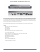
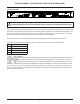
VOCIA 8-CHANNEL LIVE AUDIO INPUT DEVICE (VI-8) REAR PANEL
Network
The VI-8 is designed to be used in a single Vocia World and utilizes the Vocia CobraNet LAN to communicate with the rest of the Vocia system.
The unit has two monitored RJ45 Ethernet network connectors that allow a redundant connection to be utilized if required. The primary connection
will always have priority over the secondary connection. Monitoring of the secondary connection can be disabled in Vocia software.
The RJ45 connectors use two LEDs to indicate Ethernet link and network activity (see table below).
Left LED Right LED Description
None None No Data Connectivity or CobraNet activity
None Flashing green Link established
Solid amber Flashing green Link established and CobraNet activity detected. The unit is acting as a CobraNet Performer.
Flashing amber Flashing green Link established and CobraNet activity detected. The unit is acting as a CobraNet Conductor.
Flashing amber None CobraNetFault.Checkcablingandcongurationforerrors.
The maximum distance between any unit and an Ethernet switch is 328 feet (100 meters) when using copper cabling. Additional Ethernet
switchesand/orber-opticcablecanbeusedtofurtherextenddistancesbetweenunitsonanetwork.PleasenotethatCobraNetlimits
network extensions to seven hops (one-way transmissions) within a network.
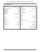
Audio Inputs
Eight balanced mic/line connections are available via eight 5.08mm 3-pin pluggable screw terminal blocks.
Pin Function
1 Audio +
2 Audio -
3 Ground (Chassis)
Control Outputs
FourrelayconnectionsareavailabletobeconguredandoperateasControlOutputs.Theconnectorsareasix-way3.5mmheaderwith
mating pluggable screw terminal block with cable restraint.
Pin Function
1 Relay C, Channel 1 or 3
2 Relay NC, Channel 1 or 3
3 Relay NO, Channel 1 or 3
4 Relay C, Channel 2 or 4
5 Relay NC, Channel 2 or 4
6 Relay NO, Channel 2 or 4